Virtio-GPIO
Virtio-gpio provides a virtual general-purpose input/output (GPIO) controller that can map native GPIOs to a User VM. The User VM can perform GPIO operations through it, including set value, get value, set direction, get direction, and set configuration. Only Open Source and Open Drain types are supported. GPIOs are often used as IRQs, typically for wakeup events. Virtio-gpio supports level and edge interrupt trigger modes.
The virtio-gpio architecture is shown below:
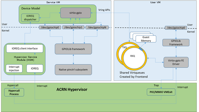
Figure 207 Virtio-gpio Architecture
Virtio-gpio is implemented as a virtio legacy device in the ACRN Device
Model (DM), and is registered as a PCI virtio device to the guest OS. No
changes are required in the frontend Linux virtio-gpio except that the
guest (User VM) kernel should be built with CONFIG_VIRTIO_GPIO=y.
Three virtqueues are used between FE and BE, one for GPIO operations, one for IRQ requests, and one for IRQ event notification.
The virtio-gpio FE driver registers a gpiochip and irqchip when it is probed. BE generates the base and number of GPIOs. Each gpiochip or irqchip operation (for example, get_direction of gpiochip or irq_set_type of irqchip) triggers a virtqueue_kick on its own virtqueue. If a GPIO has been set to interrupt mode, the interrupt events are handled within the IRQ virtqueue callback.
GPIO Mapping
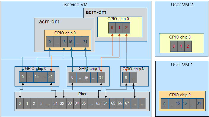
Figure 208 GPIO Mapping
Each User VM has only one GPIO chip instance. The number of GPIOs is based on the acrn-dm command line. The GPIO base always starts from 0.
Each GPIO is exclusive. A User VM can’t map the same native GPIO.
For each acrn-dm, the maximum number of GPIOs is 64.
Usage
Add the following parameters into the command line:
-s <slot>,virtio-gpio,<@controller_name{offset|name[=mapping_name]:offset|name[=mapping_name]:...}@controller_name{...}...]>
controller_name: Input
ls /sys/bus/gpio/devicesto check native GPIO controller information. Usually, the devices represent the controller_name, and you can use it as controller_name directly. You can also inputcat /sys/bus/gpio/device/XXX/devto get a device ID that can be used to match/dev/XXX, then use XXX as the controller_name. On MRB and Intel NUC platforms, the controller_name values are gpiochip0, gpiochip1, gpiochip2.gpiochip3.offset|name: You can use the GPIO offset or its name to locate one native GPIO within the GPIO controller.
mapping_name: This parameter is optional. If you want to use a customized name for a FE GPIO, you can set a new name for a FE virtual GPIO.
Example
Map three native GPIOs to the User VM. They are native gpiochip0 with offset of 1 and 6, and with the name
reset. In the User VM, the three GPIOs have no name, and base starts from 0:-s 10,virtio-gpio,@gpiochip0{1:6:reset}
Map four native GPIOs to the User VM. The native gpiochip0’s GPIO with offset 1 and offset 6 map to FE virtual GPIO with offset 0 and offset 1 without names. The native gpiochip0’s GPIO with name
resetmaps to FE virtual GPIO with offset 2 and its name isshutdown. The native gpiochip1’s GPIO with offset 0 maps to FE virtual GPIO with offset 3 and its name isreset:-s 10,virtio-gpio,@gpiochip0{1:6:reset=shutdown}@gpiochip1{0=reset}