Device Model High-Level Design
The Device Model (DM) acrn-dm is a QEMU-like application in the Service VM
responsible for creating a User VM and then performing device emulation
based on command-line configurations.
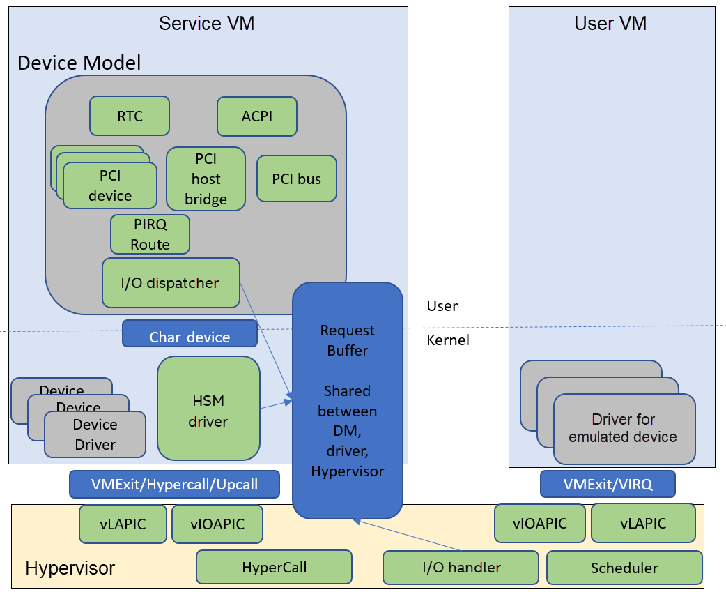
Figure 162 Device Model Framework
Figure 162 above gives a big picture overview of the DM framework. There are 3 major subsystems in the Service VM:
Device Emulation: DM provides backend device emulation routines for frontend User VM device drivers. These routines register their I/O handlers to the I/O dispatcher inside the DM. When the HSM assigns any I/O request to the DM, the I/O dispatcher dispatches this request to the corresponding device emulation routine to do the emulation.
I/O Path in Service VM:
Hypervisor initializes an I/O request and notifies the HSM driver in the Service VM through upcall.
HSM driver dispatches I/O requests to I/O clients and notifies the clients (in this case the client is the DM, which is notified through char device).
DM I/O dispatcher calls corresponding I/O handlers.
I/O dispatcher notifies the HSM driver that the I/O request is completed through char device.
HSM driver notifies the hypervisor on the completion through hypercall.
DM injects VIRQ to the User VM frontend device through hypercall.
HSM: Hypervisor Service Module is a kernel module in the Service VM and is a middle layer to support the DM. Refer to Virtio APIs for details.
This section introduces how the acrn-dm application is configured and
walks through the DM overall flow. We’ll then elaborate on device,
ISA, and PCI emulation.
Configuration
The acrn-dm runs using these command-line configuration
options:
acrn-dm [-hYv] [-B bootargs] [-E elf_image_path]
            [-k kernel_image_path]
            [-l lpc] [-m mem] [-r ramdisk_image_path]
            [-s pci] [--ovmf ovmf_file_path]
            [--enable_trusty] [--intr_monitor param_setting]
            [--acpidev_pt HID[,UID]] [--mmiodev_pt MMIO_regions]
            [--vtpm2 sock_path] [--virtio_poll interval] [--mac_seed seed_string]
            [--cpu_affinity lapic_ids] [--lapic_pt] [--rtvm] [--windows]
            [--debugexit] [--logger-setting param_setting]
            [--ssram] <vm>
    -B: bootargs for kernel
    -E: elf image path
    -h: help
    -k: kernel image path
    -l: LPC device configuration
    -m: memory size in MB
    -r: ramdisk image path
    -s: <slot,driver,configinfo> PCI slot config
    -v: version
    -Y: disable MPtable generation
    --mac_seed: set a platform unique string as a seed for generate mac address
    --ovmf: ovmf file path
    --ssram: Enable Software SRAM
    --cpu_affinity: comma-separated of Service VM vCPUs assigned to this VM. A Service VM vCPU is
         identified by its lapic ID.\n"
    --enable_trusty: enable trusty for guest
    --debugexit: enable debug exit function
    --intr_monitor: enable interrupt storm monitor
         its params: threshold/s,probe-period(s),delay_time(ms),delay_duration(ms),
    --virtio_poll: enable virtio poll mode with poll interval with ns
    --acpidev_pt: ACPI device ID args: HID,UID from the ACPI tables
    --mmiodev_pt: MMIO resources args: physical MMIO regions
    --vtpm2: Virtual TPM2 args: sock_path=$PATH_OF_SWTPM_SOCKET
    --lapic_pt: enable local apic passthrough
    --rtvm: indicate that the guest is rtvm
    --logger_setting: params like console,level=4;kmsg,level=3
    --windows: support Oracle virtio-blk, virtio-net, and virtio-input devices
         for windows guest with secure boot
    --virtio_msi: force virtio to use single-vector MSI
See Device Model Parameters for more detailed descriptions of these configuration options.
Here’s an example showing how to run a VM with:
Build ACPI table
UART device on PCI 00:01.0
GPU device on PCI 00:02.0
Virtio-block device on PCI 00:03.0
Virtio-net device on PCI 00:04.0
TPM2 MSFT0101
acrn-dm -m 2048M \
  -s 0:0,hostbridge \
  -s 1:0,lpc -l com1,stdio \
  -s 5,virtio-console,@pty:pty_port \
  -s 3,virtio-blk,/home/acrn/UserVM.img \
  -s 4,virtio-net,tap=LaaG \
  --acpidev_pt MSFT0101,00 \
  --intr_monitor 10000,10,1,100 \
  -B "root=/dev/vda2 rw rootwait maxcpus=3 nohpet console=hvc0 \
  console=ttyS0 no_timer_check ignore_loglevel log_buf_len=16M \
  consoleblank=0 tsc=reliable \
  i915.enable_hangcheck=0 i915.nuclear_pageflip=1 \
  i915.enable_guc=0" vm1
DM Initialization
Figure 163 shows the overall flow for the DM boot:
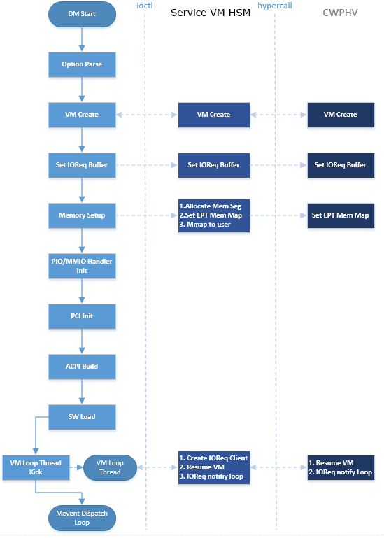
Figure 163 Device Model Boot Flow
DM Start: DM application starts to run.
Option Parsing: DM parses options from command-line inputs.
VM Create: DM calls ioctl to the Service VM HSM, then the Service VM HSM makes hypercalls to the hypervisor to create a VM. It returns a vmid for a dedicated VM.
Set I/O Request Buffer: The I/O request buffer is a page buffer allocated by the DM for a specific VM in user space. This buffer is shared among the DM, HSM, and hypervisor. Set I/O Request Buffer calls an ioctl executing a hypercall to share this unique page buffer with the HSM and hypervisor. Refer to I/O Emulation High-Level Design and I/O Emulation in Service VM for more details.
Memory Setup: User VM memory is allocated from Service VM memory. This section of memory will use Service VM hugetlbfs to allocate linear continuous host physical address for guest memory. It will try to get the page size as big as possible to guarantee maximum utilization of TLB. It then invokes a hypercall to the hypervisor for its EPT mapping, and maps the memory segments into user space.
PIO/MMIO Handler Init: PIO/MMIO handlers provide callbacks for trapped PIO/MMIO requests that are triggered from the I/O request server in the hypervisor for DM-owned device emulation. This is the endpoint of the I/O path in the DM. After this initialization, the device emulation driver in the DM can register its MMIO handler by the
register_mem()API and its PIO handler by theregister_inout()API orINOUT_PORT()macro.PCI Init: PCI initialization scans the PCI bus/slot/function to identify each configured PCI device on the
acrn-dmcommand line and initializes their configuration space by calling their dedicatedvdev_init()function. For more details on the DM PCI emulation, refer to PCI Emulation.ACPI Build: The DM will build an ACPI table into its VM’s F-Segment (0xf2400). This ACPI table includes full tables for RSDP, RSDT, XSDT, MADT, FADT, HPET, MCFG, FACS, and DSDT. All these items are programed according to the
acrn-dmcommand-line configuration and derived from their default value.SW Load: DM prepares the User VM’s software configuration such as kernel, ramdisk, and zeropage, according to these memory locations:
#define RAMDISK_LOAD_OFF(ctx)  (ctx->lowmem - 4*MB)
#define BOOTARGS_LOAD_OFF(ctx) (ctx->lowmem - 8*KB)
#define KERNEL_ENTRY_OFF(ctx)  (ctx->lowmem - 6*KB)
#define ZEROPAGE_LOAD_OFF(ctx) (ctx->lowmem - 4*KB)
#define KERNEL_LOAD_OFF(ctx)   (16*MB)
For example, if the User VM memory is set as 800M size, then SW Load will prepare its ramdisk (if there is) at 0x31c00000 (796M), bootargs at 0x31ffe000 (800M - 8K), kernel entry at 0x31ffe800 (800M - 6K), and zero page at 0x31fff000 (800M - 4K). The hypervisor will finally run the VM based on these configurations.
Note that the zero page above also includes e820 setting for this VM. The DM defines its VM e820 table according to this configuration:
/*
 * Default e820 mem map:
 *
 * there is reserved memory hole for PCI hole and APIC etc
 * so the memory layout could be separated into lowmem & highmem.
 * - if request memory size <= ctx->lowmem_limit, then there is only
 *   map[0]:0~ctx->lowmem for RAM
 *   ctx->lowmem = request_memory_size
 * - if request memory size > ctx->lowmem_limit, then there are
 *   map[0]:0~ctx->lowmem_limit & map[2]:4G~ctx->highmem for RAM
 *   ctx->highmem = request_memory_size - ctx->lowmem_limit
 *
 *            Begin     Limit           Type            Length
 * 0:             0  -  0xA0000         RAM             0xA0000
 * 1       0x100000  -  lowmem part1    RAM             0x0
 * 2:   SW SRAM_bot  -  SW SRAM_top     (reserved)      SOFTWARE_SRAM_MAX_SIZE
 * 3:   gpu_rsvd_bot -  gpu_rsvd_top    (reserved)      0x4004000
 * 4:   lowmem part2 -  0x80000000      (reserved)      0x0
 * 5:     0xE0000000 -  0x100000000     MCFG, MMIO      512MB
 * 6:  HIGHRAM_START_ADDR -  mmio64 start  RAM          ctx->highmem
 */
VM Loop Thread: DM kicks this VM loop thread to create an I/O request client for the DM, runs the VM, and enters the I/O request handling loop:
vm_loop(struct vmctx *ctx)
{
    int error;

    ctx->ioreq_client = vm_create_ioreq_client(ctx);
    if (ctx->ioreq_client < 0) {
        pr_err("%s, failed to create IOREQ.\n", __func__);
        return;
    }

    if (vm_run(ctx) != 0) {
        pr_err("%s, failed to run VM.\n", __func__);
        return;
    }

    while (1) {
        int vcpu_id;
        struct acrn_io_request *io_req;

        error = vm_attach_ioreq_client(ctx);
        if (error)
            break;

        for (vcpu_id = 0; vcpu_id < guest_ncpus; vcpu_id++) {
            io_req = &ioreq_buf[vcpu_id];
            if ((atomic_load(&io_req->processed) == ACRN_IOREQ_STATE_PROCESSING)
                && !io_req->kernel_handled)
                handle_vmexit(ctx, io_req, vcpu_id);
        }

        if (VM_SUSPEND_FULL_RESET == vm_get_suspend_mode() ||
            VM_SUSPEND_POWEROFF == vm_get_suspend_mode()) {
            break;
        }

        /* RTVM can't be reset */
        if ((VM_SUSPEND_SYSTEM_RESET == vm_get_suspend_mode()) && (!is_rtvm)) {
            vm_system_reset(ctx);
        }

        if (VM_SUSPEND_SUSPEND == vm_get_suspend_mode()) {
            vm_suspend_resume(ctx);
        }
    }
    pr_err("VM loop exit\n");
}
Mevent Dispatch Loop: It’s the final loop of the main
acrn-dmthread. mevent dispatch will do polling for potential async event.
HSM
HSM Overview
The Device Model manages a User VM by accessing interfaces exported from the HSM
module. The HSM module is a Service VM kernel driver. The /dev/acrn_hsm
node is created when the HSM module is initialized. The Device Model follows
the standard Linux char device API (ioctl) to access HSM functionality.
In most of ioctl, the HSM converts the ioctl command to a corresponding hypercall to the hypervisor. There are two exceptions:
I/O request client management is implemented in the HSM.
For memory range management of a User VM, the HSM needs to save all memory range information of the User VM. The subsequent memory mapping update of the User VM needs this information.
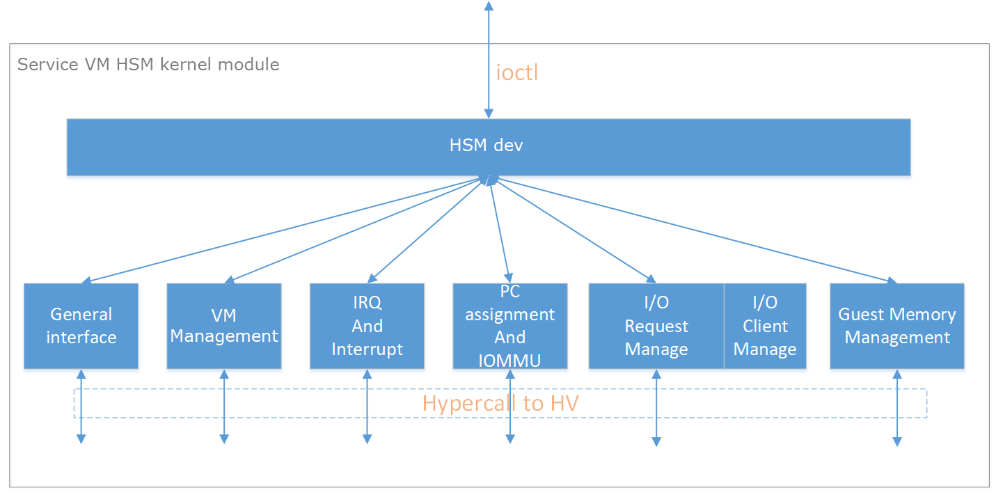
Figure 164 Architecture of ACRN HSM
HSM ioctl Interfaces
Note
Reference API documents for General interface, VM Management, IRQ and Interrupts, Device Model management, Guest Memory management, PCI assignment, and Power management.
I/O Emulation in Service VM
The HSM in the Service VM kernel dispatches I/O requests from the hypervisor to a registered client, responsible for further processing the I/O access and notifying the hypervisor on its completion.
I/O Clients
An I/O client is either a Service VM userland application or a Service VM kernel space module responsible for handling an I/O access whose address falls in a certain range. Each VM has an array of registered I/O clients that are initialized with a fixed I/O address range, plus a PCI BDF on VM creation. In each VM, a special client, called the fallback client, handles all I/O requests that do not fit into the range of any other client. In the current design, the Device Model acts as the fallback client for any VM.
Each I/O client can be configured to handle the I/O requests in the client thread context or in a separate kernel thread context. Figure 165 shows how an I/O client talks to HSM to register a handler and process the incoming I/O requests in a kernel thread specifically created for this purpose.
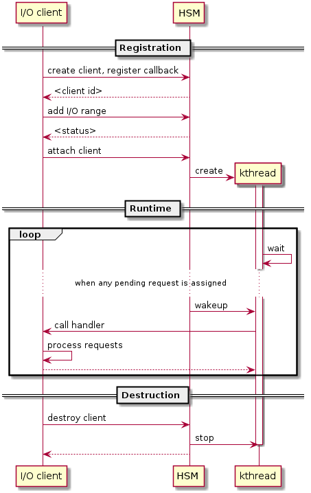
Figure 165 Interaction of In-kernel I/O Clients and HSM
On registration, the client requests a fresh ID, registers a handler, adds the I/O range (or PCI BDF) to be emulated by this client, and finally attaches it to the HSM. The HSM kicks off a new kernel thread.
The kernel thread waits for any I/O request to be handled. When the HSM assigns a pending I/O request to the client, the kernel thread wakes up and calls the registered callback function to process the request.
Before the client is destroyed, the HSM ensures that the kernel thread exits.
An I/O client can also handle I/O requests in its own thread context. Figure 166 shows the interactions in such a case, using the Device Model as an example. No callback is registered on registration and the I/O client (Device Model in the example) attaches itself to the HSM every time it is ready to process additional I/O requests. Note also that the DM runs in userland and talks to HSM via the ioctl interface in HSM ioctl interfaces.
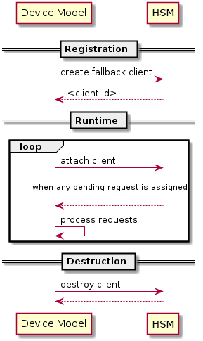
Figure 166 Interaction of DM and HSM
Refer to I/O client interfaces for a list of interfaces for developing I/O clients.
Processing I/O Requests
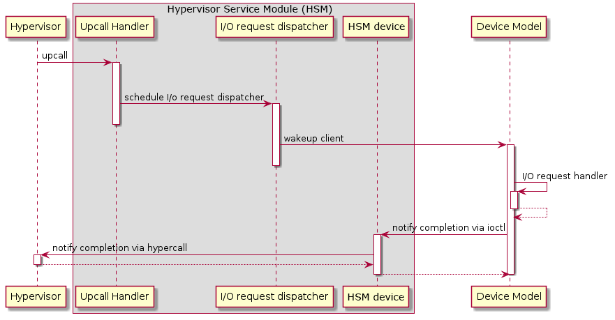
Figure 167 I/O Request Handling Sequence in Service VM
Figure 167 above illustrates the interactions among the hypervisor, HSM, and the Device Model for handling I/O requests. The main interactions are as follows:
The hypervisor makes an upcall to the Service VM as an interrupt handled by the upcall handler in HSM.
The upcall handler schedules the execution of the I/O request dispatcher. If the dispatcher is already running, another round of execution is scheduled.
The I/O request dispatcher looks for I/O requests with the PENDING state, assigns them to registered clients based on the address of the I/O access, updates their state to PROCESSING, and wakes up all clients that have I/O requests to be processed. The flow is illustrated in more detail in Figure 168.
The awakened client (the DM in Figure 167 above) handles the assigned I/O requests, updates their state to COMPLETE, and notifies the HSM of the completion via ioctl. Figure 169 shows this flow.
The HSM device notifies the hypervisor of the completion via hypercall.
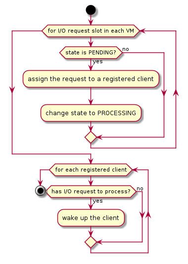
Figure 168 I/O Dispatcher Control Flow
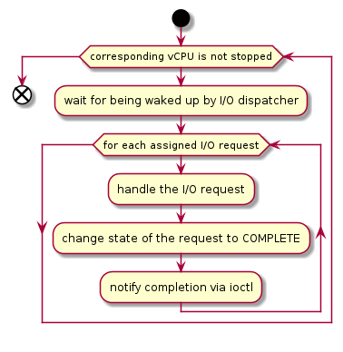
Figure 169 Device Model Control Flow on Handling I/O Requests
Emulation of Accesses to PCI Configuration Space
PCI configuration spaces are accessed by writing to an address to I/O port 0xcf8 and then reading the I/O port 0xcfc. As the PCI configuration space of different devices is emulated by different clients, HSM handles the emulation of accesses to I/O port 0xcf8, caches the BDF of the device and the offset of the register, and delivers the request to the client with the same BDF when I/O port 0xcfc is accessed.
The following table summarizes the emulation of accesses to I/O port 0xcf8 and 0xcfc.
BDF and offset cached |
BDF and offset not cached |
|
|---|---|---|
Load from 0xcf8 |
Return value previously stored to port 0xcf8 |
|
Store to 0xcf8 |
If MSB of value is 1, cache BDF and offset; otherwise, invalidate cache. |
|
Load from 0xcfc |
Assigned to client with same BDF, or fallback if not any. |
Return all 1’s |
Store to 0xcfc |
Silently ignored |
|
I/O Client Interfaces
Note
Replace with reference to API documentation.
The APIs for I/O client development are as follows:
For I/O client registration
acrn_ioreq_create_client - create ioreq client
acrn_ioreq_add_iorange - add iorange monitored by ioreq client
acrn_ioreq_intercept_bdf - set intercept bdf info of ioreq client
acrn_ioreq_get_reqbuf - get request buffer
I/O client runtime helpers.
acrn_ioreq_attach_client - start handle request for ioreq client
acrn_ioreq_complete_request - notify guest request handling is completed
For I/O client destruction
acrn_ioreq_destroy_client - destroy ioreq client
acrn_ioreq_del_iorange - del iorange monitored by ioreq client
acrn_ioreq_unintercept_bdf - clear intercept bdf info of ioreq client
Device Emulation
The DM emulates different kinds of devices, such as RTC, LPC, UART, PCI devices, and virtio block device. It is important that device emulation can handle I/O requests from different devices including PIO, MMIO, and PCI CFG SPACE access. For example, a CMOS RTC device may access 0x70/0x71 PIO to get CMOS time, a GPU PCI device may access its MMIO or PIO bar space to complete its framebuffer rendering, or the bootloader may access a PCI device’s CFG SPACE for BAR reprogramming.
The DM needs to inject interrupts/MSIs to its frontend devices whenever necessary. For example, an RTC device needs to get its ALARM interrupt, or a PCI device with MSI capability needs to get its MSI.
The DM also provides a PIRQ routing mechanism for platform devices.
PIO/MMIO/CFG SPACE Handler
This chapter provides a quick introduction of different I/O requests.
PIO Handler Register
A PIO range structure in the DM is shown below. It’s the parameter needed to register a PIO handler for a special PIO range:
Note
This should be references to API documentation in
devicemodel/include/inout.h.
struct inout_port {
        const char      *name;
        int             port;
        int             size;
        int             flags;
        inout_func_t    handler;
        void            *arg;
};
A PIO emulation handler is defined as:
/*
 * inout emulation handlers return 0 on success and -1 on failure.
 */
typedef int (*inout_func_t)(struct vmctx *ctx, int vcpu, int in, int port, int bytes, uint32_t *eax, void *arg);
The DM pre-registers the PIO emulation handlers through the macro
INOUT_PORT, or registers the PIO emulation handlers through the
register_inout() function after init_inout():
#define INOUT_PORT(name, port, flags, handler)                          \
        static struct inout_port __CONCAT(__inout_port, __LINE__) = {   \
                #name,                                                  \
                (port),                                                 \
                1,                                                      \
                (flags),                                                \
                (handler),                                              \
                0                                                       \
        };                                                              \
        DATA_SET(inout_port_set, __CONCAT(__inout_port, __LINE__))

int register_inout(struct inout_port *iop);
int unregister_inout(struct inout_port *iop);
MMIO Handler Register
An MMIO range structure is defined below. As with PIO, it’s the parameter needed to register an MMIO handler for a special MMIO range:
struct mem_range {
        const char      *name;
        int             flags;
        mem_func_t      handler;
        void            *arg1;
        long            arg2;
        uint64_t        base;
        uint64_t        size;
};
An MMIO emulation handler is defined as:
typedef int (*mem_func_t)(struct vmctx *ctx, int vcpu, int dir, uint64_t addr,
                          int size, uint64_t *val, void *arg1, long arg2);
The DM needs to call the register_mem() function to register its emulated
device’s MMIO handler:
int register_mem(struct mem_range *memp);
int unregister_mem(struct mem_range *memp);
CFG SPACE Handler Register
As HSM intercepts the cf8/cfc PIO access for PCI CFG SPACE, the DM only needs to provide CFG SPACE read/write handlers directly. Such handlers are defined as shown below. Normally, a device emulation developer has no need to update this function.
int emulate_pci_cfgrw(struct vmctx *ctx, int vcpu, int in, int bus, int slot,
        int func, int reg, int bytes, int *value)
{
        pci_cfgrw(ctx, vcpu, in, bus, slot, func, reg,
                        bytes, (uint32_t *)value);
        return 0;
}
Interrupt Interface
The DM calls these interrupt functions to send a level, edge, or MSI interrupt to destination emulated devices:
/* Generate one msi interrupt to User VM, the index parameter indicates
 * the msi number from its PCI msi capability. */
void    pci_generate_msi(struct pci_vdev *pi, int index);

/* Generate one msix interrupt to User VM, the index parameter indicates
 * the msix number from its PCI msix bar. */
void    pci_generate_msix(struct pci_vdev *pi, int index);

/* Assert INTx interrupt line to high or low. */
void    pci_lintr_assert(struct pci_vdev *pi);
void    pci_lintr_deassert(struct pci_vdev *pi);

/* Request and release the INTx interrupt resource.
 * This API will try to find one best INTx pin of this PCI slot and
 * set the "Interrupt pin" field of PCI config space. */
void    pci_lintr_request(struct pci_vdev *pi);
void    pci_lintr_release(struct pci_vdev *pi);
PIRQ Routing
Figure 170 shows a PCI device PIRQ routing example. On a platform, there could be more PCI devices than available IRQ pin resources on its PIC or IOAPIC interrupt controller. ICH hardware provides a PIRQ Routing mechanism to share IRQ pin resources between different PCI devices.
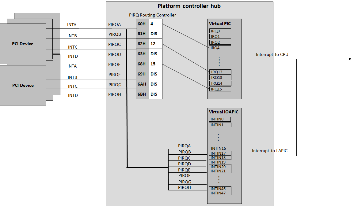
Figure 170 PIRQ Routing
The DM calls pci_lintr_route() to emulate this PIRQ routing:
static void
pci_lintr_route(struct pci_vdev *dev)
{
    struct businfo *bi;
    struct intxinfo *ii;

    if (dev->lintr.pin == 0)
        return;

    bi = pci_businfo[dev->bus];
    assert(bi != NULL);
    ii = &bi->slotinfo[dev->slot].si_intpins[dev->lintr.pin - 1];

    /*
     * Attempt to allocate an I/O APIC pin for this intpin if one
     * is not yet assigned.
     */
    if (ii->ii_ioapic_irq == 0)
        ii->ii_ioapic_irq = ioapic_pci_alloc_irq(dev);
    assert(ii->ii_ioapic_irq > 0);

    /*
     * Attempt to allocate a PIRQ pin for this intpin if one is
     * not yet assigned.
     */
    if (ii->ii_pirq_pin == 0)
        ii->ii_pirq_pin = pirq_alloc_pin(dev);
    assert(ii->ii_pirq_pin > 0);

    dev->lintr.ioapic_irq = ii->ii_ioapic_irq;
    dev->lintr.pirq_pin = ii->ii_pirq_pin;
    pci_set_cfgdata8(dev, PCIR_INTLINE, pirq_irq(ii->ii_pirq_pin));
}
The PIRQ routing for IOAPIC and PIC is dealt with differently.
For IOAPIC, the IRQ pin is allocated in a round-robin fashion within the pins permitted for PCI devices. The IRQ information will be built into the ACPI DSDT table then passed to the guest VM.
For PIC, the
pin2irqinformation is maintained in apirqs[]array (the array size is 8 representing 8 shared PIRQs). When a PCI device tries to allocate a pIRQ pin, it will do a balancing calculation to figure out a best pin vs. IRQ pair. The IRQ number will be programed into PCI INTLINE config space, and the pin number will be built into the ACPI DSDT table then passed to the guest VM.
Note
“IRQ” here is also called “GSI” in ACPI terminology.
Regarding INT A/B/C/D for PCI devices, the DM just allocates them evenly prior to pIRQ routing and then programs into PCI INTPIN config space.
ISA and PCI Emulation
ISA Emulation
There is no explicit ISA emulation structure in DM; it calls the corresponding device initialization functions directly, and takes the usage of PIO/MMIO handler and interrupt APIs (described in I/O Client Interfaces) in its routine.
PCI Emulation
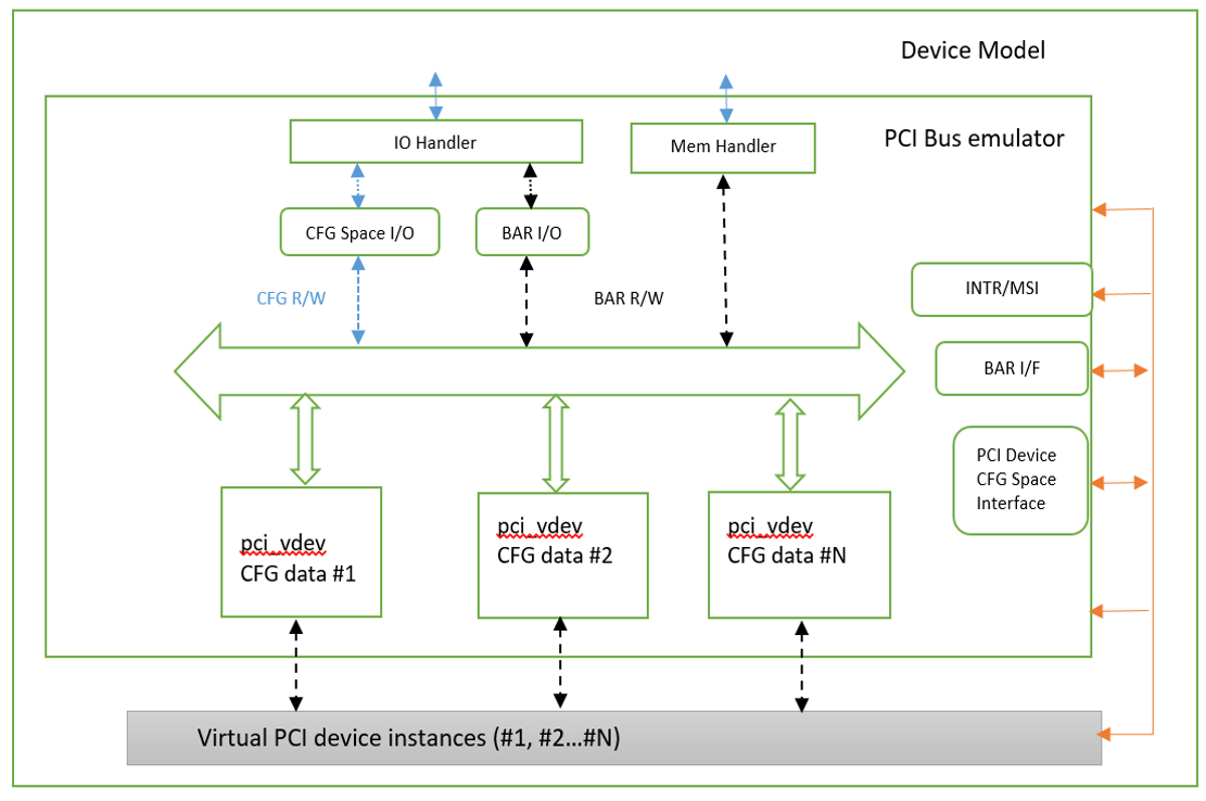
Figure 171 PCI Emulation Structure
PCI emulation takes care of three interfaces:
PCI configuration space update interface
BAR IO/MMIO handlers
INTR/MSI injection
The core PCI emulation structures are:
Note
Reference struct businfo API from devicemodel/hw/pci/core.c.
During PCI initialization, the DM will scan each PCI bus, slot, and
function and identify the PCI devices configured by acrn-dm command
line. The corresponding PCI device’s initialization function will
be called to initialize its config space, allocate its BAR resource, its
irq, and do its IRQ routing.
Note
Reference API documentation for pci_vdev, pci_vdef_ops.
The pci_vdev_ops of the pci_vdev structure could be installed by
customized handlers for cfgwrite/cfgread and barwrite/barread.
The cfgwrite/cfgread handlers will be called from the configuration space handler. The barwrite/barread will be called from the PIO/MMIO handler.
The PCI emulation device will make use of interrupt APIs as well for its interrupt injection.
PCI Host Bridge and Hierarchy
The DM provides PCI host bridge emulation. The acrn-dm command-line
input determines the bus hierarchy. Using this command line, as an
example:
acrn-dm -m 2048M \
  -s 0:0,hostbridge \
  -s 1:0,lpc -l com1,stdio \
  -s 5,virtio-console,@pty:pty_port \
  -s 3,virtio-blk,/home/acrn/UserVM.img \
  -s 4,virtio-net,tap=LaaG \
  -B "root=/dev/vda2 rw rootwait maxcpus=3 nohpet console=hvc0 \
  console=ttyS0 no_timer_check ignore_loglevel log_buf_len=16M \
  consoleblank=0 tsc=reliable \
  i915.enable_hangcheck=0 i915.nuclear_pageflip=1 \
  i915.enable_guc=0" vm1
the bus hierarchy would be:
$ lspci
00:00.0 Host bridge: Network Appliance Corporation Device 1275
00:01.0 ISA bridge: Intel Corporation 82371SB PIIX3 ISA [Natoma/Triton II]
00:03.0 SCSI storage controller: Red Hat, Inc. Virtio block device
00:04.0 Ethernet controller: Red Hat, Inc. Virtio network device
00:05.0 Serial controller: Red Hat, Inc. Virtio console
ACPI Virtualization
Introduction
Advanced Configuration and Power Interface (ACPI) provides an open standard that operating systems can use to discover and configure computer hardware components to perform power management, for example, by monitoring status and putting unused components to sleep.
Functions implemented by ACPI include:
System/Device/Processor power management
Device/Processor performance management
Configuration / Plug and Play
System event
Battery management
Thermal management
All critical functions depend on ACPI tables. On an Apollo Lake platform with Linux installed, we can see these tables using:
$ ls /sys/firmware/acpi/tables/
APIC data DMAR DSDT dynamic FACP FACS HPET MCFG NHLT TPM2
These tables provide different information and functions:
Advanced Programmable Interrupt Controller (APIC) for Symmetric Multiprocessor systems (SMP)
DMA remapping (DMAR) for Intel® Virtualization Technology for Directed I/O (VT-d)
Non-HD Audio Link Table (NHLT) for supporting audio device
Differentiated System Description Table (DSDT) for system configuration information. DSDT is a major ACPI table used to describe what peripherals the machine has, and information on PCI IRQ mappings and power management
Most of the
ACPI functionality is provided in ACPI Machine Language (AML) bytecode
stored in the ACPI tables. To make use of these tables, Linux implements
an interpreter for the AML bytecode. When the BIOS is built, AML
bytecode is compiled from the ASL (ACPI Source Language) code. To
disassemble the ACPI table, use the iasl tool:
root@:Dom0 ~ $ cp /sys/firmware/acpi/tables/DMAR .
root@:Dom0 ~ $ iasl -d DMAR

Intel ACPI Component Architecture
ASL+ Optimizing Compiler/Disassembler version 20170728
Copyright (c) 2000 - 2017 Intel Corporation
Input file DMAR, Length 0xB0 (176) bytes
ACPI: DMAR 0x0000000000000000 0000B0 (v01 INTEL  BDW      00000001 INTL 00000001)
Acpi Data Table [DMAR] decoded
Formatted output:  DMAR.dsl - 5286 bytes

root@:Dom0 ~ $ cat DMAR.dsl
[000h 0000   4]                    Signature : "DMAR"    [DMA Remapping table]
[004h 0004   4]                 Table Length : 000000B0
[008h 0008   1]                     Revision : 01
...
[030h 0048   2]                Subtable Type : 0000 [Hardware Unit Definition]
[032h 0050   2]                       Length : 0018
[034h 0052   1]                        Flags : 00
[035h 0053   1]                     Reserved : 00
[036h 0054   2]           PCI Segment Number : 0000
[038h 0056   8]        Register Base Address : 00000000FED64000
From the displayed ASL, we can see some generic table fields, such as version info, and one VT-d remapping engine description with FED64000 as base address.
We can modify DMAR.dsl and assemble it again to AML:
root@:Dom0 ~ $ iasl DMAR.dsl
Intel ACPI Component Architecture
ASL+ Optimizing Compiler/Disassembler version 20170728
Copyright (c) 2000 - 2017 Intel Corporation
Table Input: DMAR.dsl - 113 lines, 5286 bytes, 72 fields
Binary Output: DMAR.aml - 176 bytes
Compilation complete. 0 Errors, 0 Warnings, 0 Remarks
A new AML file DMAR.aml is created.
There are many ACPI tables in the system, linked together via table pointers. In all ACPI-compatible systems, the OS can enumerate all needed tables starting with the Root System Description Pointer (RSDP) provided at a known place in the system low address space, and pointing to an XSDT (Extended System Description Table). The following picture shows a typical ACPI table layout in an Apollo Lake platform:
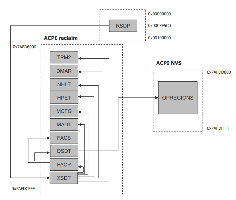
Figure 172 Typical ACPI Table Layout on Apollo Lake Platform
ACPI Virtualization
Most modern OSes require ACPI, so we need ACPI virtualization to emulate one ACPI-capable virtual platform for a guest OS. To achieve this, there are two options, depending on the method used to abstract the physical device and ACPI resources: Partitioning and Emulation.
ACPI Partitioning
One ACPI resource abstraction option is to partition all physical devices and ACPI resources between all guest OSes. That means each guest OS owns part of the devices with passthrough, as shown below:
PCI Devices |
VM0 (Cluster VM) |
VM1 (IVI VM) |
|---|---|---|
I2C |
I2C3, I2C0 |
I2C1, I2C2, I2C4, I2C5, I2C6, I2C7 |
SPI |
SPI1 |
SPI0, SPI2 |
USB |
USB-Host (xHCI) and USB-Device (xDCI) |
|
SDIO |
SDIO |
|
IPU |
IPU |
|
Ethernet |
Ethernet |
|
Wi-Fi |
Wi-Fi |
|
Bluetooth |
Bluetooth |
|
Audio |
Audio |
|
GPIO |
GPIO |
|
UART |
UART |
For simplicity, early ACRN development used partitioning. To achieve the partitions, we hacked the PCI logic to make different VMs see different subsets of devices, and create one copy of the ACPI tables for each of them, as shown here:
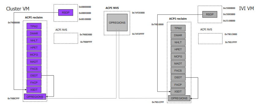
For each VM, its ACPI tables are a stand-alone copy, not related to the tables for other VMs. Opregion also must be copied for different VMs.
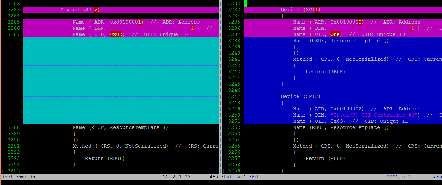
For each table, we make modifications, based on the physical table, to reflect the assigned devices to this VM. As shown in the figure below, we keep SP2(0:19.1) for VM0, and SP1(0:19.0)/SP3(0:19.2) for VM1. Any time the partition policy changes, we must modify both tables again, including disassembling, modifying, and assembling, which is tricky and potentially error-prone.
ACPI Emulation
An alternative ACPI resource abstraction option is for the Service VM to own all devices and emulate a set of virtual devices for the User VM (POST_LAUNCHED_VM). This is the most popular ACPI resource model for virtualization, as shown in the picture below. ACRN uses device emulation plus some device passthrough for the User VM.
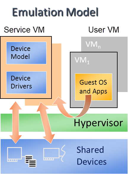
Figure 173 ACPI Emulation Model
For ACPI virtualization in ACRN, different policies are used for different components:
Hypervisor - ACPI is transparent to the hypervisor, and has no knowledge of ACPI at all.
Service VM - The Service VM owns all physical ACPI resources and enumerates all ACPI tables and devices.
User VM - Virtual ACPI resources, exposed by the Device Model, are owned by the User VM.
The ACPI emulation code of the Device Model is found in
hw/platform/acpi/acpi.c
Each entry in basl_ftables is related to each virtual ACPI table,
including the following elements:
wsect - output handler to write related ACPI table contents to specific file
offset - related ACPI table offset in the memory
valid - dynamically indicate if this table is needed
static struct {
    int (*wsect)(FILE *fp, struct vmctx *ctx);
    uint64_t  offset;
    bool    valid;
} basl_ftables[] = {
    { basl_fwrite_rsdp, 0,       true  },
    { basl_fwrite_rsdt, RSDT_OFFSET, true  },
    { basl_fwrite_xsdt, XSDT_OFFSET, true  },
    { basl_fwrite_madt, MADT_OFFSET, true  },
    { basl_fwrite_fadt, FADT_OFFSET, true  },
    { basl_fwrite_hpet, HPET_OFFSET, true  },
    { basl_fwrite_mcfg, MCFG_OFFSET, true  },
    { basl_fwrite_facs, FACS_OFFSET, true  },
    { basl_fwrite_nhlt, NHLT_OFFSET, false }, /*valid with audio ptdev*/
    { basl_fwrite_tpm2, TPM2_OFFSET, false },
    { basl_fwrite_psds, PSDS_OFFSET, false }, /*valid when psds present in Service VM */
    { basl_fwrite_dsdt, DSDT_OFFSET, true  }
};
The main function to create virtual ACPI tables is acpi_build that calls
basl_compile for each table. basl_compile does the following:
create two temp files:
infileandoutfilewith output handler, write table contents stream to
infileuse
iasltool to assembleinfileintooutfileload
outfilecontents to the required memory offset
static int
basl_compile(struct vmctx *ctx,
        int (*fwrite_section)(FILE *, struct vmctx *),
        uint64_t offset)
{
    struct basl_fio io[2];
    static char iaslbuf[3*MAXPATHLEN + 10];
    int err;

    err = basl_start(&io[0], &io[1]);
    if (!err) {
        err = (*fwrite_section)(io[0].fp, ctx);

        if (!err) {
            /*
             * iasl sends the results of the compilation to
             * stdout. Shut this down by using the shell to
             * redirect stdout to /dev/null, unless the user
             * has requested verbose output for debugging
             * purposes
             */
            if (basl_verbose_iasl)
                snprintf(iaslbuf, sizeof(iaslbuf),
                     "%s -p %s %s",
                     ASL_COMPILER,
                     io[1].f_name, io[0].f_name);
            else
                snprintf(iaslbuf, sizeof(iaslbuf),
                     "/bin/sh -c \"%s -p %s %s\" 1> /dev/null",
                     ASL_COMPILER,
                     io[1].f_name, io[0].f_name);

            err = system(iaslbuf);

            if (!err) {
                /*
                 * Copy the aml output file into guest
                 * memory at the specified location
                 */
                err = basl_load(ctx, io[1].fd, offset);
            } else
                err = -1;
        }
        basl_end(&io[0], &io[1]);
    }
After handling each entry, virtual ACPI tables are present in User VM memory.
For passthrough devices in the User VM, we may need to add some ACPI description
in the virtual DSDT table. There is one hook (passthrough_write_dsdt) in
hw/pci/passthrough.c for this. The following source code
calls different functions to add different contents for each vendor and
device id:
static void
passthru_write_dsdt(struct pci_vdev *dev)
{
    struct passthru_dev *ptdev = (struct passthru_dev *) dev->arg;
    uint32_t vendor = 0, device = 0;

    vendor = read_config(ptdev->phys_dev, PCIR_VENDOR, 2);

    if (vendor != 0x8086)
        return;

    device = read_config(ptdev->phys_dev, PCIR_DEVICE, 2);

    /* Provides ACPI extra info */
    if (device == 0x5aaa)
        /* XDCI @ 00:15.1 to enable ADB */
        write_dsdt_xhci(dev);
    else if (device == 0x5ab4)
        /* HDAC @ 00:17.0 as codec */
        write_dsdt_hdac(dev);
    else if (device == 0x5a98)
        /* HDAS @ 00:e.0 */
        write_dsdt_hdas(dev);
    else if (device == 0x5aac)
        /* i2c @ 00:16.0 for ipu */
        write_dsdt_ipu_i2c(dev);
    else if (device == 0x5abc)
        /* URT1 @ 00:18.0 for bluetooth*/
        write_dsdt_urt1(dev);
    else if (device == 0x5aca)
        /* SDC @ 00:1b.0 */
        write_dsdt_sdc(dev);

}
For instance, write_dsdt_urt1 provides ACPI contents for a Bluetooth
UART device when passed through to the User VM. It provides the virtual PCI
device/function as _ADR. With another description, it could be used for
Bluetooth UART enumeration.
static void
write_dsdt_urt1(struct pci_vdev *dev)
{
    printf("write virt-%x:%x.%x in dsdt for URT1 @ 00:18.0\n",
           dev->bus,
           dev->slot,
           dev->func);
    dsdt_line("Device (URT1)");
    dsdt_line("{");
    dsdt_line("    Name (_ADR, 0x%04X%04X)", dev->slot, dev->func);
    dsdt_line("    Name (_DDN, \"Intel(R) HS-UART Controller #1\")");
    dsdt_line("    Name (_UID, One)");
    dsdt_line("    Name (RBUF, ResourceTemplate ()");
    dsdt_line("    {");
    dsdt_line("    })");
    dsdt_line("    Method (_CRS, 0, NotSerialized)");
    dsdt_line("    {");
    dsdt_line("        Return (RBUF)");
    dsdt_line("    }");
    dsdt_line("}");
}
PM in Device Model
The power management (PM) module in the Device Model emulates the User VM low-power state transition.
Each time the User VM writes an ACPI control register to initialize low-power state transition, the writing operation is trapped to the DM as an I/O emulation request by the I/O emulation framework.
To emulate User VM S5 entry, the DM destroys the I/O request client, releases allocated User VM memory, stops all created threads, destroys the User VM, and exits the DM. To emulate S5 exit, a fresh DM started by the VM manager is used.
To emulate User VM S3 entry, the DM pauses the User VM, stops the User VM watchdog, and waits for a resume signal. When the User VM should exit from S3, the DM gets a wakeup signal and resets the User VM to emulate the User VM exit from S3.
Passthrough in Device Model
Refer to Device Passthrough for passthrough realization in the Device Model and MMIO Device Passthrough for MMIO passthrough realization in the Device Model and ACRN hypervisor.