I/O Emulation high-level design
As discussed in Device Emulation, there are multiple ways and places to handle I/O emulation, including HV, SOS Kernel VHM, and SOS user-land device model (acrn-dm).
I/O emulation in the hypervisor provides these functionalities:
- Maintain lists of port I/O or MMIO handlers in the hypervisor for emulating trapped I/O accesses in a certain range.
- Forward I/O accesses to SOS when they cannot be handled by the hypervisor by any registered handlers.
Figure 146 illustrates the main control flow steps of I/O emulation inside the hypervisor:
- Trap and decode I/O access by VM exits and decode the access from exit qualification or by invoking the instruction decoder.
- If the range of the I/O access overlaps with any registered handler, call that handler if it completely covers the range of the access, or ignore the access if the access crosses the boundary.
- If the range of the I/O access does not overlap the range of any I/O handler, deliver an I/O request to SOS.
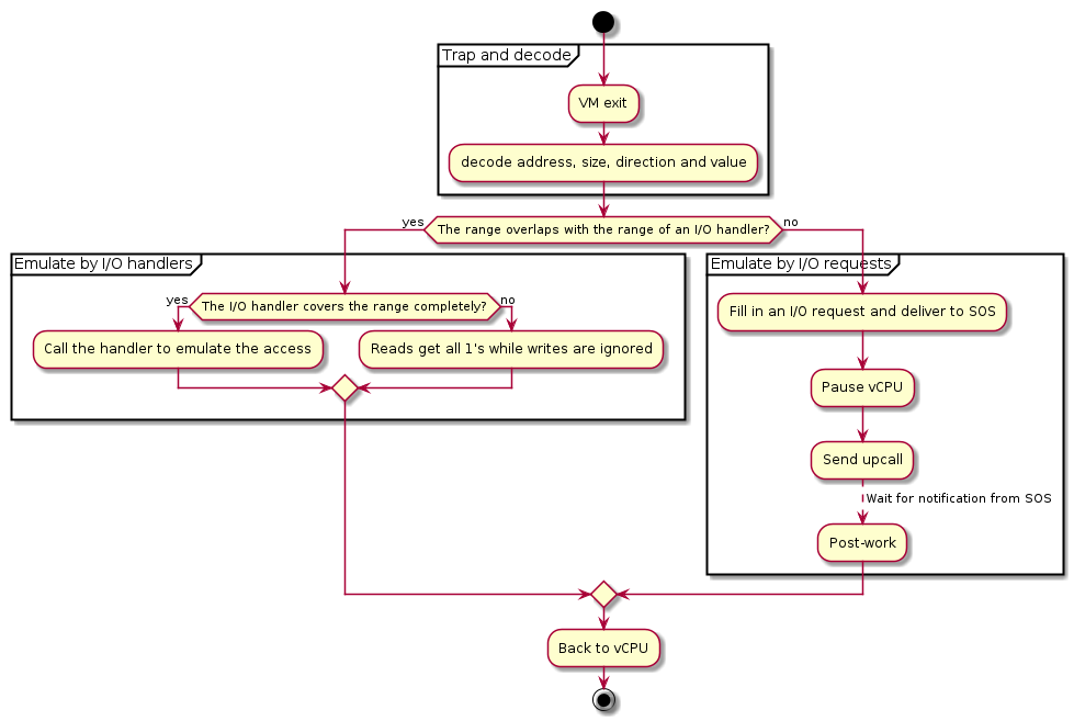
Figure 146 Control flow of I/O emulation in the hypervisor
I/O emulation does not rely on any calibration data.
Trap Path
Port I/O accesses are trapped by VM exits with the basic exit reason “I/O instruction”. The port address to be accessed, size, and direction (read or write) are fetched from the VM exit qualification. For writes the value to be written to the I/O port is fetched from guest registers al, ax or eax, depending on the access size.
MMIO accesses are trapped by VM exits with the basic exit reason “EPT violation”. The instruction emulator is invoked to decode the instruction that triggers the VM exit to get the memory address being accessed, size, direction (read or write), and the involved register.
The I/O bitmaps and EPT are used to configure the addresses that will trigger VM exits when accessed by a VM. Refer to IO/MMIO Emulation for details.
I/O Emulation in the Hypervisor
When a port I/O or MMIO access is trapped, the hypervisor first checks whether the to-be-accessed address falls in the range of any registered handler, and calls the handler when such a handler exists.
Handler Management
Each VM has two lists of I/O handlers, one for port I/O and the other for MMIO. Each element of the list contains a memory range and a pointer to the handler which emulates the accesses falling in the range. See Initialization and Deinitialization for descriptions of the related data structures.
The I/O handlers are registered on VM creation and never changed until the destruction of that VM, when the handlers are unregistered. If multiple handlers are registered for the same address, the one registered later wins. See Initialization and Deinitialization for the interfaces used to register and unregister I/O handlers.
I/O Dispatching
When a port I/O or MMIO access is trapped, the hypervisor first walks through the corresponding I/O handler list in the reverse order of registration, looking for a proper handler to emulate the access. The following cases exist:
- If a handler whose range overlaps the range of the I/O access is
found,
- If the range of the I/O access falls completely in the range the handler can emulate, that handler is called.
- Otherwise it is implied that the access crosses the boundary of multiple devices which the hypervisor does not emulate. Thus no handler is called and no I/O request will be delivered to SOS. I/O reads get all 1’s and I/O writes are dropped.
- If the range of the I/O access does not overlap with any range of the handlers, the I/O access is delivered to SOS as an I/O request for further processing.
I/O Requests
An I/O request is delivered to SOS vCPU 0 if the hypervisor does not find any handler that overlaps the range of a trapped I/O access. This section describes the initialization of the I/O request mechanism and how an I/O access is emulated via I/O requests in the hypervisor.
Initialization
For each UOS the hypervisor shares a page with SOS to exchange I/O requests. The 4-KByte page consists of 16 256-Byte slots, indexed by vCPU ID. It is required for the DM to allocate and set up the request buffer on VM creation, otherwise I/O accesses from UOS cannot be emulated by SOS, and all I/O accesses not handled by the I/O handlers in the hypervisor will be dropped (reads get all 1’s).
Refer to the following sections for details on I/O requests and the initialization of the I/O request buffer.
Types of I/O Requests
There are four types of I/O requests:
| I/O Request Type | Description |
|---|---|
| PIO | A port I/O access. |
| MMIO | A MMIO access to a GPA with no mapping in EPT. |
| PCI | A PCI configuration space access. |
| WP | A MMIO access to a GPA with a read-only mapping in EPT. |
For port I/O accesses, the hypervisor will always deliver an I/O request of type PIO to SOS. For MMIO accesses, the hypervisor will deliver an I/O request of either MMIO or WP, depending on the mapping of the accessed address (in GPA) in the EPT of the vCPU. The hypervisor will never deliver any I/O request of type PCI, but will handle such I/O requests in the same ways as port I/O accesses on their completion.
Refer to Data Structures and Interfaces for a detailed description of the data held by each type of I/O request.
I/O Request State Transitions
Each slot in the I/O request buffer is managed by a finite state machine with four states. The following figure illustrates the state transitions and the events that trigger them.
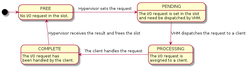
Figure 147 State Transition of I/O Requests
The four states are:
- FREE
- The I/O request slot is not used and new I/O requests can be delivered. This is the initial state on UOS creation.
- PENDING
- The I/O request slot is occupied with an I/O request pending to be processed by SOS.
- PROCESSING
- The I/O request has been dispatched to a client but the client has not finished handling it yet.
- COMPLETE
- The client has completed the I/O request but the hypervisor has not consumed the results yet.
The contents of an I/O request slot are owned by the hypervisor when the state of an I/O request slot is FREE or COMPLETE. In such cases SOS can only access the state of that slot. Similarly the contents are owned by SOS when the state is PENDING or PROCESSING, when the hypervisor can only access the state of that slot.
The states are transferred as follow:
- To deliver an I/O request, the hypervisor takes the slot corresponding to the vCPU triggering the I/O access, fills the contents, changes the state to PENDING and notifies SOS via upcall.
- On upcalls, SOS dispatches each I/O request in the PENDING state to clients and changes the state to PROCESSING.
- The client assigned an I/O request changes the state to COMPLETE after it completes the emulation of the I/O request. A hypercall is made to notify the hypervisor on I/O request completion after the state change.
- The hypervisor finishes the post-work of a I/O request after it is notified on its completion and change the state back to FREE.
States are accessed using atomic operations to avoid getting unexpected states on one core when it is written on another.
Note that there is no state to represent a ‘failed’ I/O request. SOS should return all 1’s for reads and ignore writes whenever it cannot handle the I/O request, and change the state of the request to COMPLETE.
Post-work
After an I/O request is completed, some more work needs to be done for I/O reads to update guest registers accordingly. Currently the hypervisor re-enters the vCPU thread every time a vCPU is scheduled back in, rather than switching to where the vCPU is scheduled out. As a result, post-work is introduced for this purpose.
The hypervisor pauses a vCPU before an I/O request is delivered to SOS. Once the I/O request emulation is completed, a client notifies the hypervisor by a hypercall. The hypervisor will pick up that request, do the post-work, and resume the guest vCPU. The post-work takes care of updating the vCPU guest state to reflect the effect of the I/O reads.
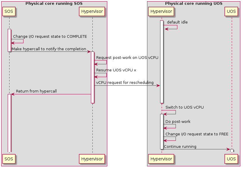
Figure 148 Workflow of MMIO I/O request completion
The figure above illustrates the workflow to complete an I/O request for MMIO. Once the I/O request is completed, SOS makes a hypercall to notify the hypervisor which resumes the UOS vCPU triggering the access after requesting post-work on that vCPU. After the UOS vCPU resumes, it does the post-work first to update the guest registers if the access reads an address, changes the state of the corresponding I/O request slot to FREE, and continues execution of the vCPU.
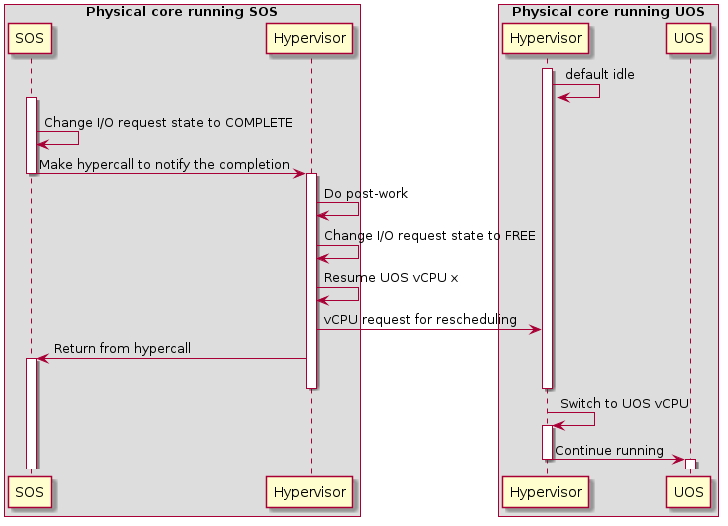
Figure 149 Workflow of port I/O request completion
Completion of a port I/O request (shown in Figure 149 above) is similar to the MMIO case, except the post-work is done before resuming the vCPU. This is because the post-work for port I/O reads need to update the general register eax of the vCPU, while the post-work for MMIO reads need further emulation of the trapped instruction. This is much more complex and may impact the performance of SOS.
Data Structures and Interfaces
External Interfaces
The following structures represent an I/O request. struct vhm_request is the main structure and the others are detailed representations of I/O requests of different kinds.
-
struct
mmio_request Representation of a MMIO request.
Public Members
-
uint32_t
direction Direction of the access.
Either
REQUEST_READorREQUEST_WRITE.
-
uint32_t
reserved reserved
-
uint64_t
address Address of the I/O access.
-
uint64_t
size Width of the I/O access in byte.
-
uint64_t
value The value read for I/O reads or to be written for I/O writes.
-
uint32_t
-
struct
pio_request Representation of a port I/O request.
Public Members
-
uint32_t
direction Direction of the access.
Either
REQUEST_READorREQUEST_WRITE.
-
uint32_t
reserved reserved
-
uint64_t
address Port address of the I/O access.
-
uint64_t
size Width of the I/O access in byte.
-
uint32_t
value The value read for I/O reads or to be written for I/O writes.
-
uint32_t
-
struct
pci_request Representation of a PCI configuration space access.
Public Members
-
uint32_t
direction Direction of the access.
Either
REQUEST_READorREQUEST_WRITE.
-
uint32_t
reserved[3] Reserved.
-
int64_t
size Width of the I/O access in byte.
-
int32_t
value The value read for I/O reads or to be written for I/O writes.
-
int32_t
bus The
buspart of the BDF of the device.
-
int32_t
dev The
devicepart of the BDF of the device.
-
int32_t
func The
functionpart of the BDF of the device.
-
int32_t
reg The register to be accessed in the configuration space.
-
uint32_t
-
union
vhm_io_request - #include <acrn_common.h>
Public Members
-
struct pio_request
pio
-
struct pci_request
pci
-
struct mmio_request
mmio
-
int64_t
reserved1[8]
-
struct pio_request
-
struct
vhm_request 256-byte VHM requests
The state transitions of a VHM request are:
FREE -> PENDING -> PROCESSING -> COMPLETE -> FREE -> …
When a request is in COMPLETE or FREE state, the request is owned by the hypervisor. SOS (VHM or DM) shall not read or write the internals of the request except the state.
When a request is in PENDING or PROCESSING state, the request is owned by SOS. The hypervisor shall not read or write the request other than the state.
Based on the rules above, a typical VHM request lifecycle should looks like the following.
SOS vCPU 0 SOS vCPU x UOS vCPU y Hypervisor:
- Fill in type, addr, etc.
- Pause UOS vCPU y
- Set state to PENDING (a)
- Fire upcall to SOS vCPU 0
VHM:
- Scan for pending requests
- Set state to PROCESSING (b)
- Assign requests to clients (c)
Client:
- Scan for assigned requests
- Handle the requests (d)
- Set state to COMPLETE
- Notify the hypervisor
Hypervisor:
- resume UOS vCPU y (e)
Hypervisor:
- Post-work (f)
- set state to FREE
Note that the following shall hold.
- (a) happens before (b)
- (c) happens before (d)
- (e) happens before (f)
- One vCPU cannot trigger another I/O request before the previous one has completed (i.e. the state switched to FREE)
Accesses to the state of a vhm_request shall be atomic and proper barriers are needed to ensure that:
- Setting state to PENDING is the last operation when issuing a request in the hypervisor, as the hypervisor shall not access the request any more.
- Due to similar reasons, setting state to COMPLETE is the last operation of request handling in VHM or clients in SOS.
Public Members
-
uint32_t
type Type of this request.
Byte offset: 0.
-
uint32_t
completion_polling Hypervisor will poll completion if set.
Byte offset: 4.
-
uint32_t
reserved0[14] Reserved.
Byte offset: 8.
-
union vhm_io_request
reqs Details about this request.
For REQ_PORTIO, this has type pio_request. For REQ_MMIO and REQ_WP, this has type mmio_request. For REQ_PCICFG, this has type pci_request.
Byte offset: 64.
-
uint32_t
reserved1 Reserved.
Byte offset: 128.
-
int32_t
client The client which is distributed to handle this request.
Accessed by VHM only.
Byte offset: 132.
-
uint32_t
processed The status of this request.
Taking REQ_STATE_xxx as values.
Byte offset: 136.
For hypercalls related to I/O emulation, refer to I/O Emulation in the Hypervisor.
Initialization and Deinitialization
The following structure represents a port I/O handler:
-
struct
vm_io_handler_desc¶ Describes a single IO handler description entry.
Public Members
-
uint16_t
port_start¶ The base port number of the IO range for this description.
-
uint16_t
port_end¶ The last port number of the IO range for this description (non-inclusive).
-
io_read_fn_t
io_read¶ A pointer to the “read” function.
The read function is called from the hypervisor whenever a read access to a range described in “ranges” occur. The arguments to the callback are:
- The address of the port to read from.
- The width of the read operation (1,2 or 4).
The implementation must return the ports content as byte, word or doubleword (depending on the width).
If the pointer is null, a read of 1’s is assumed.
-
io_write_fn_t
io_write¶ A pointer to the “write” function.
The write function is called from the hypervisor code whenever a write access to a range described in “ranges” occur. The arguments to the callback are:
- The address of the port to write to.
- The width of the write operation (1,2 or 4).
- The value to write as byte, word or doubleword (depending on the width)
The implementation must write the value to the port.
If the pointer is null, the write access is ignored.
-
uint16_t
The following structure represents a MMIO handler.
-
struct
mem_io_node¶ Structure for MMIO handler node.
Public Members
-
bool
hold_lock¶ Whether the lock needs to hold when handle the MMIO access.
-
hv_mem_io_handler_t
read_write¶ A pointer to the handler.
The function for handling MMIO accesses to the specified range.
-
void *
handler_private_data¶ Private data used by the handler.
The pointer to any data specified at registration. This pointer is passed to the handler whenever the handler is called.
-
struct list_head
list¶ The struct to make a bi-directional linked list.
-
uint64_t
range_start¶ The starting address.
This member is used in pair with
range_end. See the documentation ofrange_endfor details.
-
uint64_t
range_end¶ The ending address.
range_start(inclusive) andrange_end(exclusive) together specify the address range that this handler is expected to emulate. Note that the bytes to be accessed shall completely fall in the range before the handler is called to emulate that access, or more specificallyrange_start<= address < address + size <=endwhere address and size are the starting address of the MMIO access and the number of bytes to be accessed, respectively. Otherwise the behavior is undefined.
-
bool
The following APIs are provided to initialize, deinitialize or configure I/O bitmaps and register or unregister I/O handlers:
-
void
allow_guest_pio_access(struct acrn_vm *vm, uint16_t port_address, uint32_t nbytes)¶ Allow a VM to access a port I/O range.
This API enables direct access from the given
vmto the port I/O space starting fromport_addresstoport_address+nbytes- 1.- Parameters
vm: The VM whose port I/O access permissions is to be changedport_address: The start address of the port I/O rangenbytes: The size of the range, in bytes
-
void
register_pio_emulation_handler(struct acrn_vm *vm, uint32_t pio_idx, const struct vm_io_range *range, io_read_fn_t io_read_fn_ptr, io_write_fn_t io_write_fn_ptr)¶ Register a port I/O handler.
- Preconditions
- pio_idx < EMUL_PIO_IDX_MAX
- Parameters
vm: The VM to which the port I/O handlers are registeredpio_idx: The emulated port io indexrange: The emulated port io rangeio_read_fn_ptr: The handler for emulating reads from the given rangeio_write_fn_ptr: The handler for emulating writes to the given range
-
void
register_mmio_emulation_handler(struct acrn_vm *vm, hv_mem_io_handler_t read_write, uint64_t start, uint64_t end, void *handler_private_data, bool hold_lock)¶ Register a MMIO handler.
This API registers a MMIO handler to
vm.- Return
- None
- Parameters
vm: The VM to which the MMIO handler is registeredread_write: The handler for emulating accesses to the given rangestart: The base address of the rangeread_writecan emulateend: The end of the range (exclusive)read_writecan emulatehandler_private_data: Handler-specific data which will be passed toread_writewhen calledhold_lock: Whether hold the lock to handle the MMIO access
I/O Emulation
The following APIs are provided for I/O emulation at runtime:
-
int32_t
acrn_insert_request(struct acrn_vcpu *vcpu, const struct io_request *io_req)¶ Deliver
io_reqto SOS and suspendvcputill its completion.- Preconditions
- vcpu != NULL && io_req != NULL
- Parameters
vcpu: The virtual CPU that triggers the MMIO accessio_req: The I/O request holding the details of the MMIO access
-
int32_t
pio_instr_vmexit_handler(struct acrn_vcpu *vcpu)¶ The handler of VM exits on I/O instructions.
- Parameters
vcpu: The virtual CPU which triggers the VM exit on I/O instruction
-
int32_t
ept_violation_vmexit_handler(struct acrn_vcpu *vcpu)¶ EPT violation handling.
- Parameters
vcpu: the pointer that points to vcpu data structure
- Return Value
-EINVAL: fail to handle the EPT violation0: Success to handle the EPT violation