RDT Configuration
On x86 platforms that support Intel Resource Director Technology (RDT) allocation features such as Cache Allocation Technology (CAT) and Memory Bandwidth Allocation (MBA), the ACRN hypervisor can be used to limit regular VMs which may be over-utilizing common resources such as cache and memory bandwidth relative to their priorities so that the performance of other higher priorities VMs (such as RTVMs) are not impacted.
Using RDT includes three steps:
- Detect and enumerate RDT allocation capabilites on supported resources such as cache and memory bandwidth.
- Set up resource mask array MSRs (Model-Specific Registers) for each CLOS (Class of Service, which is a resource allocation), basically to limit or allow access to resource usage.
- Select the CLOS for the CPU associated with the VM that will apply the resource mask on the CP.
Steps #2 and #3 configure RDT resources for a VM and can be done in two ways:
- Using a HV debug shell (See Tuning RDT resources in HV debug shell)
- Using a VM configuration (See Configure RDT for VM using VM Configuration)
The following sections discuss how to detect, enumerate capabilities, and configure RDT resources for VMs in the ACRN hypervisor.
For further details, refer to the ACRN RDT high-level design RDT Allocation Feature Supported by Hypervisor and Intel 64 and IA-32 Architectures Software Developer’s Manual, (Section 17.19 Intel Resource Director Technology Allocation Features)
RDT detection and resource capabilites
From the ACRN HV debug shell, use cpuid to detect and identify the
resource capabilities. Use the platform’s serial port for the HV shell
(refer to Getting started guide for UP2 board for setup instructions).
Check if the platform supports RDT with cpuid. First, run cpuid 0x7 0x0; the return value ebx [bit 15] is set to 1 if the platform supports
RDT. Next, run cpuid 0x10 0x0 and check the EBX [3-1] bits. EBX [bit 1]
indicates that L3 CAT is supported. EBX [bit 2] indicates that L2 CAT is
supported. EBX [bit 3] indicates that MBA is supported. To query the
capabilties of the supported resources, use the bit position as a subleaf
index. For example, run cpuid 0x10 0x2 to query the L2 CAT capability.
ACRN:\>cpuid 0x7 0x0
cpuid leaf: 0x7, subleaf: 0x0, 0x0:0xd39ffffb:0x00000818:0xbc000400
L3/L2 bit encoding:
EAX [bit 4:0] reports the length of the cache mask minus one. For example, a value 0xa means the cache mask is 0x7ff.
EBX [bit 31:0] reports a bit mask. Each set bit indicates the corresponding unit of the cache allocation that can be used by other entities in the platform (e.g. integrated graphics engine).
ECX [bit 2] if set, indicates that cache Code and Data Prioritization Technology is supported.
EDX [bit 15:0] reports the maximum CLOS supported for the resource minus one. For example, a value of 0xf means the max CLOS supported is 0x10.
ACRN:\>cpuid 0x10 0x0
cpuid leaf: 0x10, subleaf: 0x0, 0x0:0xa:0x0:0x0

ACRN:\>cpuid 0x10 **0x1**
cpuid leaf: 0x10, subleaf: 0x1, 0xa:0x600:0x4:0xf
MBA bit encoding:
EAX [bit 11:0] reports the maximum MBA throttling value minus one. For example, a value 0x59 means the max delay value is 0x60.
EBX [bit 31:0] reserved.
ECX [bit 2] reports whether the response of the delay values is linear.
EDX [bit 15:0] reports the maximum CLOS supported for the resource minus one. For example, a value of 0x7 means the max CLOS supported is 0x8.
ACRN:\>cpuid 0x10 0x0
cpuid leaf: 0x10, subleaf: 0x0, 0x0:0xa:0x0:0x0

ACRN:\>cpuid 0x10 **0x3**
cpuid leaf: 0x10, subleaf: 0x3, 0x59:0x0:0x4:0x7
Tuning RDT resources in HV debug shell
This section explains how to configure the RDT resources from the HV debug shell.
Check the PCPU IDs of each VM; the
vcpu_listbelow shows that VM0 is running on PCPU0, and VM1 is running on PCPU1:ACRN:\>vcpu_list VM ID PCPU ID VCPU ID VCPU ROLE VCPU STATE ===== ======= ======= ========= ========== 0 0 0 PRIMARY Running 1 1 0 PRIMARY Running
Set the resource mask array MSRs for each CLOS with a
wrmsr <reg_num> <value>. For example, if you want to restrict VM1 to use the lower 4 ways of LLC cache and you want to allocate the upper 7 ways of LLC to access to VM0, you must first assign a CLOS for each VM (e.g. VM0 is assigned CLOS0 and VM1 CLOS1). Next, resource mask the MSR that corresponds to the CLOS0. In our example, IA32_L3_MASK_BASE + 0 is programmed to 0x7f0. Finally, resource mask the MSR that corresponds to CLOS1. In our example, IA32_L3_MASK_BASE + 1 is set to 0xf.ACRN:\>wrmsr -p1 0xc90 0x7f0 ACRN:\>wrmsr -p1 0xc91 0xf
Assign CLOS1 to PCPU1 by programming the MSR IA32_PQR_ASSOC [bit 63:32] (0xc8f) to 0x100000000 to use CLOS1 and assign CLOS0 to PCPU 0 by programming MSR IA32_PQR_ASSOC [bit 63:32] to 0x0. Note that IA32_PQR_ASSOC is per LP MSR and CLOS must be programmed on each LP.
ACRN:\>wrmsr   -p0   0xc8f    0x000000000 (this is default and can be skipped)
ACRN:\>wrmsr   -p1   0xc8f    0x100000000
Configure RDT for VM using VM Configuration
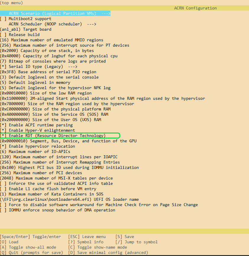
RDT on ACRN is enabled by default on supported platforms. This information can be found using an offline tool that generates a platform-specific xml file that helps ACRN identify RDT-supported platforms. This feature can be also be toggled using the CONFIG_RDT_ENABLED flag with the
make menuconfigcommand. The first step is to clone the ACRN source code (if you haven’t already done so):$ git clone https://github.com/projectacrn/acrn-hypervisor.git $ cd acrn-hypervisor/
The predefined cache masks can be found at
hypervisor/arch/x86/configs/$(CONFIG_BOARD)/board.cfor respective boards. For example, apl-up2 can found athypervisor/arch/x86/configs/apl-up2/board.c.struct platform_clos_info platform_l2_clos_array[MAX_PLATFORM_CLOS_NUM] = { { .clos_mask = 0xff, .msr_index = MSR_IA32_L3_MASK_BASE + 0, }, { .clos_mask = 0xff, .msr_index = MSR_IA32_L3_MASK_BASE + 1, }, { .clos_mask = 0xff, .msr_index = MSR_IA32_L3_MASK_BASE + 2, }, { .clos_mask = 0xff, .msr_index = MSR_IA32_L3_MASK_BASE + 3, }, };Note
Users can change the mask values, but the cache mask must have continuous bits or a #GP fault can be triggered. Similary, when programming an MBA delay value, be sure to set the value to less than or equal to the MAX delay value.
Set up the CLOS in the VM config. Follow RDT detection and resource capabilites to identify the MAX CLOS that can be used. ACRN uses the the lowest common MAX CLOS value among all RDT resources to avoid resource misconfigurations. For example, configuration data for the Service VM sharing mode can be found at
hypervisor/arch/x86/configs/vm_config.cstruct acrn_vm_config vm_configs[CONFIG_MAX_VM_NUM] __aligned(PAGE_SIZE) = { { .type = SOS_VM, .name = SOS_VM_CONFIG_NAME, .guest_flags = 0UL, .clos = 1, .memory = { .start_hpa = 0x0UL, .size = CONFIG_SOS_RAM_SIZE, }, .os_config = { .name = SOS_VM_CONFIG_OS_NAME, }, }, };Note
In ACRN, Lower CLOS always means higher priority (clos 0 > clos 1 > clos 2>…clos n). So, carefully program each VM’s CLOS accordingly.
Careful consideration should be made when assigning vCPU affinity. In a cache isolation configuration, in addition to isolating CAT-capable caches, you must also isolate lower-level caches. In the following example, logical processor #0 and #2 share L1 and L2 caches. In this case, do not assign LP #0 and LP #2 to different VMs that need to do cache isolation. Assign LP #1 and LP #3 with similar consideration:
# lstopo-no-graphics -v
Package L#0 (P#0 CPUVendor=GenuineIntel CPUFamilyNumber=6 CPUModelNumber=142)
  L3Cache L#0 (size=3072KB linesize=64 ways=12 Inclusive=1)
    L2Cache L#0 (size=256KB linesize=64 ways=4 Inclusive=0)
      L1dCache L#0 (size=32KB linesize=64 ways=8 Inclusive=0)
        L1iCache L#0 (size=32KB linesize=64 ways=8 Inclusive=0)
          Core L#0 (P#0)
            PU L#0 (P#0)
            PU L#1 (P#2)
    L2Cache L#1 (size=256KB linesize=64 ways=4 Inclusive=0)
      L1dCache L#1 (size=32KB linesize=64 ways=8 Inclusive=0)
        L1iCache L#1 (size=32KB linesize=64 ways=8 Inclusive=0)
          Core L#1 (P#1)
            PU L#2 (P#1)
            PU L#3 (P#3)
Bandwidth control is per-core (not per LP), so max delay values of per-LP CLOS is applied to the core. If HT is turned on, don’t place high priority threads on sibling LPs running lower priority threads.
Based on our scenario, build the ACRN hypervisor and copy the artifact
acrn.efito the/boot/EFI/acrndirectory. If needed, update the devicemodelacrn-dmas well in/usr/bindirectory. see Build ACRN from Source for building instructions.$ make hypervisor BOARD=apl-up2 FIRMWARE=uefi ... # these operations are done on UP2 board $ mount /dev/mmcblk0p0 /boot $ scp <acrn.efi-at-your-compile-PC> /boot/EFI/acrn
Restart the platform.