What is ACRN
Introduction to Project ACRN
ACRN™ is a, flexible, lightweight reference hypervisor, built with real-time and safety-criticality in mind, and optimized to streamline embedded development through an open source platform. ACRN defines a device hypervisor reference stack and an architecture for running multiple software subsystems, managed securely, on a consolidated system by means of a virtual machine manager (VMM). It also defines a reference framework implementation for virtual device emulation, called the “ACRN Device Model”.
The ACRN Hypervisor is a Type 1 reference hypervisor stack, running directly on the bare-metal hardware, and is suitable for a variety of IoT and embedded device solutions. The ACRN hypervisor addresses the gap that currently exists between datacenter hypervisors, and hard partitioning hypervisors. The ACRN hypervisor architecture partitions the system into different functional domains, with carefully selected user VM sharing optimizations for IoT and embedded devices.
ACRN Open Source Roadmap 2020
Stay informed on what’s ahead for ACRN in 2020 by visting the ACRN 2020 Roadmap.
For up-to-date happenings, visit the ACRN blog.
ACRN High-Level Architecture
The ACRN architecture has evolved since it’s initial v0.1 release in July 2018. Beginning with the v1.1 release, the ACRN architecture has flexibility to support partition mode, sharing mode, and a mixed hybrid mode. As shown in Figure 1, hardware resources can be partitioned into two parts:
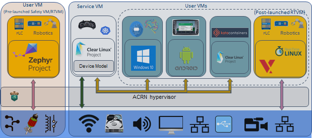
Figure 1 ACRN high-level architecture
Shown on the left of Figure 1, resources are partitioned and used by a pre-launched user virtual machine (VM). Pre-launched here means that it is launched by the hypervisor directly, even before the service VM is launched. The pre-launched VM runs independently of other virtual machines and owns dedicated hardware resources, such as a CPU core, memory, and I/O devices. Other virtual machines may not even be aware of the pre-launched VM’s existence. Because of this, it can be used as a safety OS virtual machine. Platform hardware failure detection code runs inside this pre-launched VM and will take emergency actions when system critical failures occur.
Shown on the right of Figure 1, the remaining hardware resources are shared among the service VM and user VMs. The service VM is similar to Xen’s Dom0, and a user VM is similar to Xen’s DomU. The service VM is the first VM launched by ACRN, if there is no pre-launched VM. The service VM can access hardware resources directly by running native drivers and it provides device sharing services to the user VMs through the Device Model. Currently, the service VM is based on Linux, but it can also use other operating systems as long as the ACRN Device Model is ported into it. A user VM can be Clear Linux*, Android*, Windows* or VxWorks*. There is one special user VM, called a post-launched Real-Time VM (RTVM), designed to run a hard real-time OS, such as VxWorks*, or Xenomai*. Because of its real-time capability, RTVM can be used for soft programmable logic controller (PLC), inter-process communication (IPC), or Robotics applications.
Usage Scenarios
ACRN can be used for heterogeneous workload consolidation in resource-constrained embedded platform, targeting for functional safety, or hard real-time support. It can take multiple separate systems and enable a workload consolidation solution operating on a single compute platform to run both safety-critical applications and non-safety applications, together with security functions that safeguard the system.
Automotive Application Scenarios
As shown in Figure 2, the ACRN hypervisor can be used for building Automotive Software Defined Cockpit (SDC) and In-Vehicle Experience (IVE) solutions.
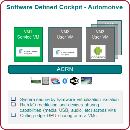
Figure 2 ACRN Automotive SDC scenario
As a reference implementation, ACRN provides the basis for embedded hypervisor vendors to build solutions with a reference I/O mediation solution. In this scenario, an automotive SDC system consists of the Instrument Cluster (IC) system in VM1, the In-Vehicle Infotainment (IVI) system in VM2, and one or more Rear Seat Entertainment (RSE) systems in VM3. Each system is running as an isolated Virtual Machine (VM) for overall system safety considerations.
An Instrument Cluster (IC) system is used to show the driver operational information about the vehicle, such as:
- the speed, fuel level, trip mileage, and other driving information of the car;
- projecting heads-up images on the windshield, with alerts for low fuel or tire pressure;
- showing rear-view and surround-view cameras for parking assistance.
An In-Vehicle Infotainment (IVI) system’s capabilities can include:
- navigation systems, radios, and other entertainment systems;
- connection to mobile devices for phone calls, music, and applications via voice recognition;
- control interaction by gesture recognition or touch.
A Rear Seat Entertainment (RSE) system could run:
- entertainment system;
- virtual office;
- connection to the front-seat IVI system and mobile devices (cloud connectivity);
- connection to mobile devices for phone calls, music, and applications via voice recognition;
- control interaction by gesture recognition or touch.
The ACRN hypervisor can support both Linux* VM and Android* VM as User VMs managed by the ACRN hypervisor. Developers and OEMs can use this reference stack to run their own VMs, together with IC, IVI, and RSE VMs. The Service VM runs in the background and the User VMs run as Post-Launched VMs.
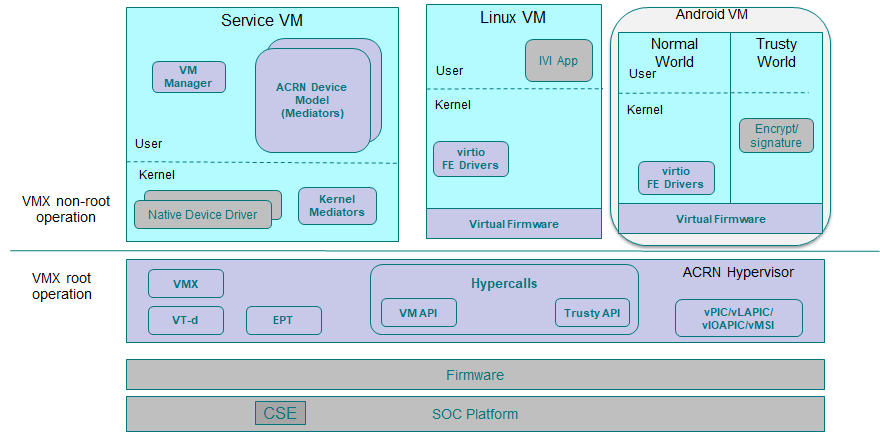
Figure 3 ACRN SDC usage architecture overview
A block diagram of ACRN’s SDC usage scenario is shown in Figure 3 above.
- The ACRN hypervisor sits right on top of the bootloader for fast booting capabilities.
- Resources are partitioned to ensure safety-critical and non-safety-critical domains are able to coexist on one platform.
- Rich I/O mediators allows sharing of various I/O devices across VMs, delivering a comprehensive user experience.
- Multiple operating systems are supported by one SoC through efficient virtualization.
Industrial Workload Consolidation
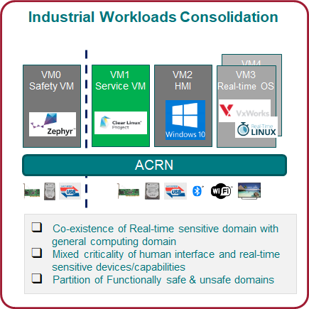
Figure 4 ACRN Industrial Workload Consolidation scenario
Supporting Workload consolidation for industrial applications is even more challenging. The ACRN hypervisor needs to run both safety-critical and non-safety workloads with no interference, increase security functions that safeguard the system, run hard real-time sensitive workloads together with general computing workloads, and conduct data analytics for timely actions and predictive maintenance.
Virtualization is especially important in industrial environments because of device and application longevity. Virtualization enables factories to modernize their control system hardware by using VMs to run older control systems and operating systems far beyond their intended retirement dates.
As shown in Figure 5, the Safety VM has functional safety applications running inside it to monitor the overall system health status. This Safety VM is partitioned from other VMs and is pre-launched before the Service VM. Service VM provides devices sharing capability across user VMs and can launch additional user VMs. In this usage example, VM2 provides Human Machine Interface (HMI) capability, and VM3 is optimized to support industrial workload real-time OS needs, such as VxWorks* or RT-Linux*.
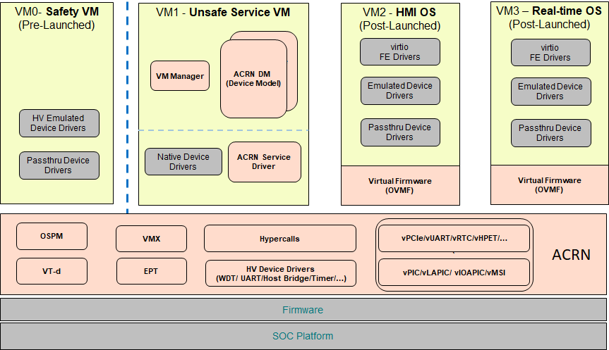
Figure 5 ACRN Industrial Usage Architecture Overview
Figure 5 shows ACRN’s block diagram for an Industrial usage scenario:
- ACRN boots from the SoC platform, and supports firmware such as the UEFI BIOS.
- The ACRN hypervisor can create four VMs to run four different OSes:
- A safety VM such as Zephyr*,
- a service VM such as Clear Linux*,
- a Human Machine Interface (HMI) application OS such as Windows*, and
- a real-time control OS such as VxWorks or RT-Linux*.
- The Safety VM (VM0) is launched by ACRN before any other VM. The functional safety code inside VM0 checks the overall system health status.
- The Service VM, provides device sharing functionalities, such as disk and network mediation, to other virtual machines. It can also run an orchestration agent allowing User VM orchestration with tools such as Kubernetes*.
- The HMI Application OS can be Windows* or Linux*. Windows is dominant in Industrial HMI environments.
- ACRN can support a soft Real-time OS such as preempt-rt Linux for soft-PLC control, or a hard Real-time OS that offers less jitter.
Best Known Configurations
The ACRN Github codebase defines five best known configurations (BKC) targeting SDC and Industry usage scenarios. Developers can start with one of these pre-defined configurations and customize it to their own application scenario needs. (These configurations assume there is at most one Safety VM and it is pre-launched.)
| Pre-defined BKC | Usage Scenario | VM0 | VM1 | VM2 | VM3 |
|---|---|---|---|---|---|
| Software Defined Cockpit 1 | SDC | Service VM | Post-launched VM (Android) | ||
| Software Defined Cockpit 2 | SDC | Service VM | Post-launched VM (Android) | Post-launched VM (Android) | Post-launched VM (Android) |
| Industry Usage Config 1 | Industry | Service VM | Post-launched VM (HMI) | Post-launched VM (Hard RTVM) | Post-launched VM (Soft RTVM) |
| Industry Usage Config 2 | Industry | Pre-launched VM (Safety VM) | Service VM | Post-launched VM (HMI) | Post-launched VM (Hard/Soft RTVM) |
| Logical Partition | Logical Partition | Pre-launched VM (Safety VM) | Pre-launched VM (QM Linux VM) |
Here are block diagrams for each of these five scenarios.
SDC scenario with two VMs
In this SDC scenario, an Instrument Cluster (IC) system runs with the Service VM and an In-Vehicle Infotainment (IVI) system runs in a user VM.
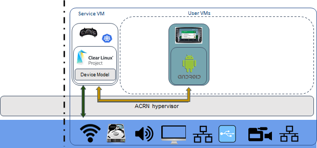
Figure 6 SDC scenario with two VMs
SDC scenario with four VMs
In this SDC scenario, an Instrument Cluster (IC) system runs with the Service VM. An In-Vehicle Infotainment (IVI) is User VM1 and two Rear Seat Entertainment (RSE) systems run in User VM2 and User VM3.
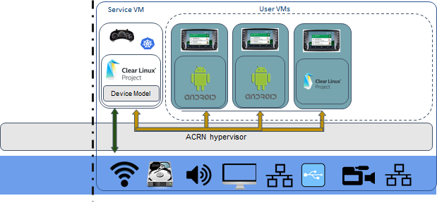
Figure 7 SDC scenario with four VMs
Industry scenario without a safety VM
In this Industry scenario, the Service VM provides device sharing capability for a Windows-based HMI User VM. The other two post-launched User VMs support either hard or soft Real-time OS applications.
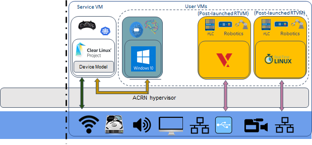
Figure 8 Industry scenario without a safety VM
Industry scenario with a safety VM
In this Industry scenario, a Pre-launched VM is included as a Safety VM. The Service VM provides device sharing capability for the HMI User VM. The remaining User VM can support either a hard or soft Real-time OS application.
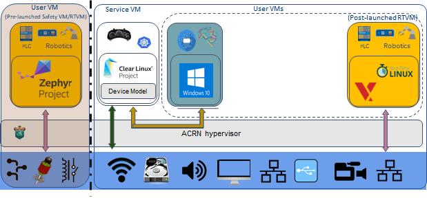
Figure 9 Industry scenario with a safety VM
Logical Partitioning scenario
This scenario is a simplified VM configuration for VM logical partitioning: one is the Safety VM and the other is a Linux-based User VM.
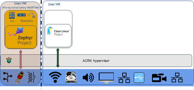
Figure 10 Logical Partitioning scenario
Licensing
Both the ACRN hypervisor and ACRN Device model software are provided under the permissive BSD-3-Clause license, which allows “redistribution and use in source and binary forms, with or without modification” together with the intact copyright notice and disclaimers noted in the license.
ACRN Device Model, Service VM, and User VM
To keep the hypervisor code base as small and efficient as possible, the bulk of the device model implementation resides in the Service VM to provide sharing and other capabilities. The details of which devices are shared and the mechanism used for their sharing is described in pass-through section below.
The Service VM runs with the system’s highest virtual machine priority to ensure required device time-sensitive requirements and system quality of service (QoS). Service VM tasks run with mixed priority. Upon a callback servicing a particular User VM request, the corresponding software (or mediator) in the Service VM inherits the User VM priority. There may also be additional low-priority background tasks within the Service OS.
In the automotive example we described above, the User VM is the central hub of vehicle control and in-vehicle entertainment. It provides support for radio and entertainment options, control of the vehicle climate control, and vehicle navigation displays. It also provides connectivity options for using USB, Bluetooth, and Wi-Fi for third-party device interaction with the vehicle, such as Android Auto* or Apple CarPlay*, and many other features.
Boot Sequence
ACRN supports two kinds of boots: De-privilege boot mode and Direct boot mode.
De-privilege boot mode
De-privilege boot mode is loaded by acrn.efi under a UEFI
environment. The Service VM must be the first launched VM, (i.e. VM0).
In Figure 11, we show a verified Boot Sequence with UEFI on an Intel Architecture platform NUC (see Supported Hardware).

Figure 11 ACRN Hypervisor De-privilege boot mode Flow
The Boot process proceeds as follows:
- UEFI verifies and boots the ACRN hypervisor and Service VM Bootloader.
- UEFI (or Service VM Bootloader) verifies and boots the Service VM kernel.
- The Service VM kernel verifies and loads the ACRN Device Model and the Virtual
bootloader through
dm-verity. - The virtual bootloader starts the User-side verified boot process.
Note
To avoid a hardware resources conflict with the ACRN hypervisor, UEFI services shall not use IOMMU. In addition, we only currently support the UEFI timer with the HPET MSI.
In this boot mode, both the Service and User VM boot options (e.g. Linux command-line parameters) are configured following the instructions for the EFI bootloader used by the Operating System (OS).
- In the case of Clear Linux, the EFI bootloader is systemd-boot and the Linux
kernel command-line parameters are defined in the
.conffiles. - Another popular EFI bootloader used by Linux distributions is grub. Distributions like Ubuntu/Debian, Fedora/CentOS use grub.
Note
The Slim Bootloader is an alternative boot firmware that can be used to boot ACRN. The Boot ACRN Hyervisor tutorial provides more information on how to use SBL with ACRN.
Note
A virtual Slim Bootloader, called vSBL,
can also be used to start User VMs. The Device Model Parameters provides more information
on how to boot a User VM using vSBL. Note that in this case, the kernel command-line parameters are
defined by the combination of the cmdline.txt passed on to the iasimage script and in the launch script, via the -B option.
Direct boot mode
In Figure 12, we show the Direct boot mode sequence:

Figure 12 ACRN Hypervisor Direct boot mode Boot Flow
The Boot process proceeds as follows:
- UEFI boots GRUB.
- GRUB boots the ACRN hypervisor and loads the VM kernels as Multi-boot modules.
- The ACRN hypervisor verifies and boots kernels of the Pre-launched VM and Service VM.
- In the Service VM launch path, the Service VM kernel verifies and loads
the ACRN Device Model and Virtual bootloader through
dm-verity. - The virtual bootloader starts the User-side verified boot process.
In this boot mode, the boot options are defined via the VM{x}_CONFIG_OS_BOOTARGS
macro in the source code (replace {x} with the VM number).
ACRN Hypervisor Architecture
ACRN hypervisor is a Type 1 hypervisor, running directly on bare-metal hardware. It implements a hybrid VMM architecture, using a privileged service VM, running the Service VM that manages the I/O devices and provides I/O mediation. Multiple User VMs are supported, with each of them running Linux* or Android* OS as the User VM .
Running systems in separate VMs provides isolation between other VMs and their applications, reducing potential attack surfaces and minimizing safety interference. However, running the systems in separate VMs may introduce additional latency for applications.
Figure 13 shows the ACRN hypervisor architecture, with the automotive example IC VM and service VM together. The Service VM owns most of the devices including the platform devices, and provides I/O mediation. Some of the PCIe devices may be passed through to the User OSes via the VM configuration. The Service VM runs the IC applications and hypervisor-specific applications together, such as the ACRN device model, and ACRN VM manager.
ACRN hypervisor also runs the ACRN VM manager to collect running information of the User OS, and controls the User VM such as starting, stopping, and pausing a VM, pausing or resuming a virtual CPU.

Figure 13 ACRN Hypervisor Architecture
ACRN hypervisor takes advantage of Intel Virtualization Technology (Intel VT), and ACRN hypervisor runs in Virtual Machine Extension (VMX) root operation, or host mode, or VMM mode. All the guests, including User VM and Service VM, run in VMX non-root operation, or guest mode. (Hereafter, we use the terms VMM mode and Guest mode for simplicity).
The VMM mode has 4 protection rings, but runs the ACRN hypervisor in ring 0 privilege only, leaving rings 1-3 unused. The guest (including Service VM and User VM), running in Guest mode, also has its own four protection rings (ring 0 to 3). The User kernel runs in ring 0 of guest mode, and user land applications run in ring 3 of User mode (ring 1 & 2 are usually not used by commercial OSes).
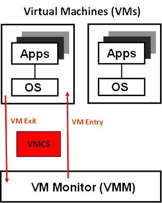
Figure 14 VMX Brief
As shown in Figure 14, VMM mode and guest mode are switched through VM Exit and VM Entry. When the bootloader hands off control to the ACRN hypervisor, the processor hasn’t enabled VMX operation yet. The ACRN hypervisor needs to enable VMX operation thru a VMXON instruction first. Initially, the processor stays in VMM mode when the VMX operation is enabled. It enters guest mode thru a VM resume instruction (or first time VM launch), and returns back to VMM mode thru a VM exit event. VM exit occurs in response to certain instructions and events.
The behavior of processor execution in guest mode is controlled by a virtual machine control structure (VMCS). VMCS contains the guest state (loaded at VM Entry, and saved at VM Exit), the host state, (loaded at the time of VM exit), and the guest execution controls. ACRN hypervisor creates a VMCS data structure for each virtual CPU, and uses the VMCS to configure the behavior of the processor running in guest mode.
When the execution of the guest hits a sensitive instruction, a VM exit event may happen as defined in the VMCS configuration. Control goes back to the ACRN hypervisor when the VM exit happens. The ACRN hypervisor emulates the guest instruction (if the exit was due to privilege issue) and resumes the guest to its next instruction, or fixes the VM exit reason (for example if a guest memory page is not mapped yet) and resume the guest to re-execute the instruction.
Note that the address space used in VMM mode is different from that in guest mode. The guest mode and VMM mode use different memory mapping tables, and therefore the ACRN hypervisor is protected from guest access. The ACRN hypervisor uses EPT to map the guest address, using the guest page table to map from guest linear address to guest physical address, and using the EPT table to map from guest physical address to machine physical address or host physical address (HPA).
ACRN Device Model Architecture
Because devices may need to be shared between VMs, device emulation is used to give VM applications (and OSes) access to these shared devices. Traditionally there are three architectural approaches to device emulation:
- The first architecture is device emulation within the hypervisor which is a common method implemented within the VMware* workstation product (an operating system-based hypervisor). In this method, the hypervisor includes emulations of common devices that the various guest operating systems can share, including virtual disks, virtual network adapters, and other necessary platform elements.
- The second architecture is called user space device emulation. As the name implies, rather than the device emulation being embedded within the hypervisor, it is instead implemented in a separate user space application. QEMU, for example, provides this kind of device emulation also used by a large number of independent hypervisors. This model is advantageous, because the device emulation is independent of the hypervisor and can therefore be shared for other hypervisors. It also permits arbitrary device emulation without having to burden the hypervisor (which operates in a privileged state) with this functionality.
- The third variation on hypervisor-based device emulation is paravirtualized (PV) drivers. In this model introduced by the XEN project the hypervisor includes the physical drivers, and each guest operating system includes a hypervisor-aware driver that works in concert with the hypervisor drivers.
In the device emulation models discussed above, there’s a price to pay for sharing devices. Whether device emulation is performed in the hypervisor, or in user space within an independent VM, overhead exists. This overhead is worthwhile as long as the devices need to be shared by multiple guest operating systems. If sharing is not necessary, then there are more efficient methods for accessing devices, for example “pass-through”.
ACRN device model is a placeholder of the User VM. It allocates memory for the User OS, configures and initializes the devices used by the User VM, loads the virtual firmware, initializes the virtual CPU state, and invokes the ACRN hypervisor service to execute the guest instructions. ACRN Device model is an application running in the Service VM that emulates devices based on command line configuration, as shown in the architecture diagram Figure 15 below:
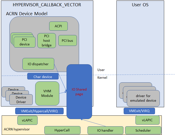
Figure 15 ACRN Device Model
ACRN Device model incorporates these three aspects:
- Device Emulation:
- ACRN Device model provides device emulation routines that register their I/O handlers to the I/O dispatcher. When there is an I/O request from the User VM device, the I/O dispatcher sends this request to the corresponding device emulation routine.
- I/O Path:
- see ACRN-io-mediator below
- VHM:
The Virtio and Hypervisor Service Module is a kernel module in the Service VM acting as a middle layer to support the device model. The VHM and its client handling flow is described below:
- ACRN hypervisor IOREQ is forwarded to the VHM by an upcall notification to the Service VM.
- VHM will mark the IOREQ as “in process” so that the same IOREQ will not pick up again. The IOREQ will be sent to the client for handling. Meanwhile, the VHM is ready for another IOREQ.
- IOREQ clients are either an Service VM Userland application or a Service VM Kernel space module. Once the IOREQ is processed and completed, the Client will issue an IOCTL call to the VHM to notify an IOREQ state change. The VHM then checks and hypercalls to ACRN hypervisor notifying it that the IOREQ has completed.
Note
Userland: dm as ACRN Device Model.
Kernel space: VBS-K, MPT Service, VHM itself
Device pass through
At the highest level, device pass-through is about providing isolation of a device to a given guest operating system so that the device can be used exclusively by that guest.
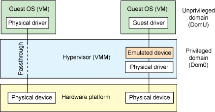
Figure 16 Device Passthrough
Near-native performance can be achieved by using device passthrough. This is ideal for networking applications (or those with high disk I/O needs) that have not adopted virtualization because of contention and performance degradation through the hypervisor (using a driver in the hypervisor or through the hypervisor to a user space emulation). Assigning devices to specific guests is also useful when those devices inherently wouldn’t be shared. For example, if a system includes multiple video adapters, those adapters could be passed through to unique guest domains.
Finally, there may be specialized PCI devices that only one guest domain uses, so they should be passed through to the guest. Individual USB ports could be isolated to a given domain too, or a serial port (which is itself not shareable) could be isolated to a particular guest. In ACRN hypervisor, we support USB controller Pass through only and we don’t support pass through for a legacy serial port, (for example 0x3f8).
Hardware support for device passthrough
Intel’s current processor architectures provides support for device pass-through with VT-d. VT-d maps guest physical address to machine physical address, so device can use guest physical address directly. When this mapping occurs, the hardware takes care of access (and protection), and the guest operating system can use the device as if it were a non-virtualized system. In addition to mapping guest to physical memory, isolation prevents this device from accessing memory belonging to other guests or the hypervisor.
Another innovation that helps interrupts scale to large numbers of VMs is called Message Signaled Interrupts (MSI). Rather than relying on physical interrupt pins to be associated with a guest, MSI transforms interrupts into messages that are more easily virtualized (scaling to thousands of individual interrupts). MSI has been available since PCI version 2.2 but is also available in PCI Express (PCIe), where it allows fabrics to scale to many devices. MSI is ideal for I/O virtualization, as it allows isolation of interrupt sources (as opposed to physical pins that must be multiplexed or routed through software).
Hypervisor support for device passthrough
By using the latest virtualization-enhanced processor architectures, hypervisors and virtualization solutions can support device pass-through (using VT-d), including Xen, KVM, and ACRN hypervisor. In most cases, the guest operating system (User OS) must be compiled to support pass-through, by using kernel build-time options. Hiding the devices from the host VM may also be required (as is done with Xen using pciback). Some restrictions apply in PCI, for example, PCI devices behind a PCIe-to-PCI bridge must be assigned to the same guest OS. PCIe does not have this restriction.
ACRN I/O mediator
Figure 17 shows the flow of an example I/O emulation path.
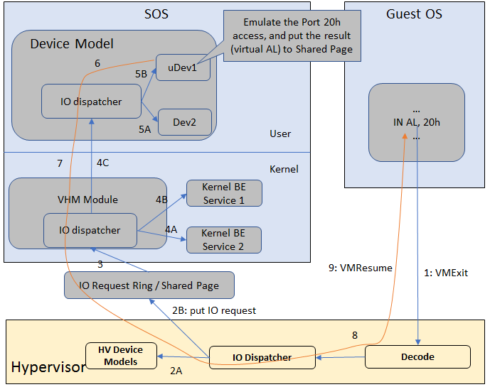
Figure 17 I/O Emulation Path
Following along with the numbered items in Figure 17:
- When a guest execute an I/O instruction (PIO or MMIO), a VM exit happens. ACRN hypervisor takes control, and analyzes the the VM exit reason, which is a VMX_EXIT_REASON_IO_INSTRUCTION for PIO access.
- ACRN hypervisor fetches and analyzes the guest instruction, and
notices it is a PIO instruction (
in AL, 20hin this example), and put the decoded information (including the PIO address, size of access, read/write, and target register) into the shared page, and notify/interrupt the Service VM to process. - The Virtio and hypervisor service module (VHM) in Service VM receives the interrupt, and queries the IO request ring to get the PIO instruction details.
- It checks to see if any kernel device claims ownership of the IO port: if a kernel module claimed it, the kernel module is activated to execute its processing APIs. Otherwise, the VHM module leaves the IO request in the shared page and wakes up the device model thread to process.
- The ACRN device model follow the same mechanism as the VHM. The I/O processing thread of device model queries the IO request ring to get the PIO instruction details and checks to see if any (guest) device emulation module claims ownership of the IO port: if a module claimed it, the module is invoked to execute its processing APIs.
- After the ACRN device module completes the emulation (port IO 20h access in this example), (say uDev1 here), uDev1 puts the result into the shared page (in register AL in this example).
- ACRN device model then returns control to ACRN hypervisor to indicate the completion of an IO instruction emulation, typically thru VHM/hypercall.
- The ACRN hypervisor then knows IO emulation is complete, and copies the result to the guest register context.
- The ACRN hypervisor finally advances the guest IP to indicate completion of instruction execution, and resumes the guest.
The MMIO path is very similar, except the VM exit reason is different. MMIO access usually is trapped thru VMX_EXIT_REASON_EPT_VIOLATION in the hypervisor.
Virtio framework architecture
Virtio is an abstraction for a set of common emulated devices in any type of hypervisor. In the ACRN reference stack, our implementation is compatible with Virtio spec 0.9 and 1.0. By following this spec, virtual environments and guests should have a straightforward, efficient, standard and extensible mechanism for virtual devices, rather than boutique per-environment or per-OS mechanisms.
Virtio provides a common frontend driver framework which not only standardizes device interfaces, but also increases code reuse across different virtualization platforms.
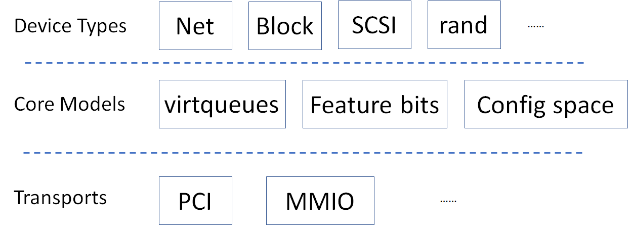
Figure 18 Virtio Architecture
To better understand Virtio, especially its usage in the ACRN project, several key concepts of Virtio are highlighted here:
- Front-End Virtio driver (a.k.a. frontend driver, or FE driver in this document)
- Virtio adopts a frontend-backend architecture, which enables a simple but flexible framework for both frontend and backend Virtio driver. The FE driver provides APIs to configure the interface, pass messages, produce requests, and notify backend Virtio driver. As a result, the FE driver is easy to implement and the performance overhead of emulating device is eliminated.
- Back-End Virtio driver (a.k.a. backend driver, or BE driver in this document)
- Similar to FE driver, the BE driver, runs either in user-land or kernel-land of host OS. The BE driver consumes requests from FE driver and send them to the host’s native device driver. Once the requests are done by the host native device driver, the BE driver notifies the FE driver about the completeness of the requests.
- Straightforward: Virtio devices as standard devices on existing Buses
- Instead of creating new device buses from scratch, Virtio devices are built on existing buses. This gives a straightforward way for both FE and BE drivers to interact with each other. For example, FE driver could read/write registers of the device, and the virtual device could interrupt FE driver, on behalf of the BE driver, in case of something is happening. Currently Virtio supports PCI/PCIe bus and MMIO bus. In ACRN project, only PCI/PCIe bus is supported, and all the Virtio devices share the same vendor ID 0x1AF4.
- Efficient: batching operation is encouraged
- Batching operation and deferred notification are important to achieve high-performance I/O, since notification between FE and BE driver usually involves an expensive exit of the guest. Therefore batching operating and notification suppression are highly encouraged if possible. This will give an efficient implementation for the performance critical devices.
- Standard: virtqueue
All the Virtio devices share a standard ring buffer and descriptor mechanism, called a virtqueue, shown in Figure 6. A virtqueue is a queue of scatter-gather buffers. There are three important methods on virtqueues:
add_bufis for adding a request/response buffer in a virtqueueget_bufis for getting a response/request in a virtqueue, andkickis for notifying the other side for a virtqueue to consume buffers.
The virtqueues are created in guest physical memory by the FE drivers. The BE drivers only need to parse the virtqueue structures to obtain the requests and get the requests done. How virtqueue is organized is specific to the User OS. In the implementation of Virtio in Linux, the virtqueue is implemented as a ring buffer structure called vring.
In ACRN, the virtqueue APIs can be leveraged directly so users don’t need to worry about the details of the virtqueue. Refer to the User VM for more details about the virtqueue implementations.
- Extensible: feature bits
- A simple extensible feature negotiation mechanism exists for each virtual device and its driver. Each virtual device could claim its device specific features while the corresponding driver could respond to the device with the subset of features the driver understands. The feature mechanism enables forward and backward compatibility for the virtual device and driver.
In the ACRN reference stack, we implement user-land and kernel space as shown in Figure 19:
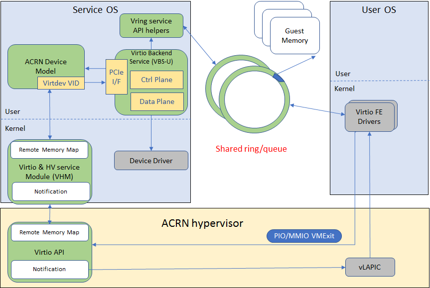
Figure 19 Virtio Framework - User Land
In the Virtio user-land framework, the implementation is compatible with Virtio Spec 0.9/1.0. The VBS-U is statically linked with Device Model, and communicates with Device Model through the PCIe interface: PIO/MMIO or MSI/MSIx. VBS-U accesses Virtio APIs through user space vring service API helpers. User space vring service API helpers access shared ring through remote memory map (mmap). VHM maps User VM memory with the help of ACRN Hypervisor.
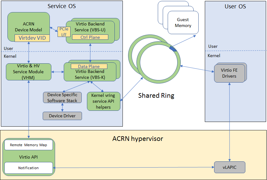
Figure 20 Virtio Framework - Kernel Space
VBS-U offloads data plane processing to VBS-K. VBS-U initializes VBS-K at the right timings, for example. The FE driver sets VIRTIO_CONFIG_S_DRIVER_OK to avoid unnecessary device configuration changes while running. VBS-K can access shared rings through VBS-K virtqueue APIs. VBS-K virtqueue APIs are similar to VBS-U virtqueue APIs. VBS-K registers as VHM client(s) to handle a continuous range of registers
There may be one or more VHM-clients for each VBS-K, and there can be a single VHM-client for all VBS-Ks as well. VBS-K notifies FE through VHM interrupt APIs.