Security high-level design
Introduction
This document describes security high-level design in ACRN, including information about:
- Secure booting in ACRN
- Hypervisor security enhancement, including memory management, secure hypervisor interfaces, etc.
- Platform security features virtualization, such as the virtualization of TPM (vTPM) and SGX (vSGX)
This document is for developers, validation teams, architects, and maintainers of ACRN.
Readers should be familiar with the basic concepts of system virtualization and the ACRN hypervisor implementation.
Background
The ACRN hypervisor is a type-1 hypervisor, built for running multiple guest OS instances, typical of an automotive infotainment system, on a single Intel Apollo Lake-I SoC platform. See Figure 275.
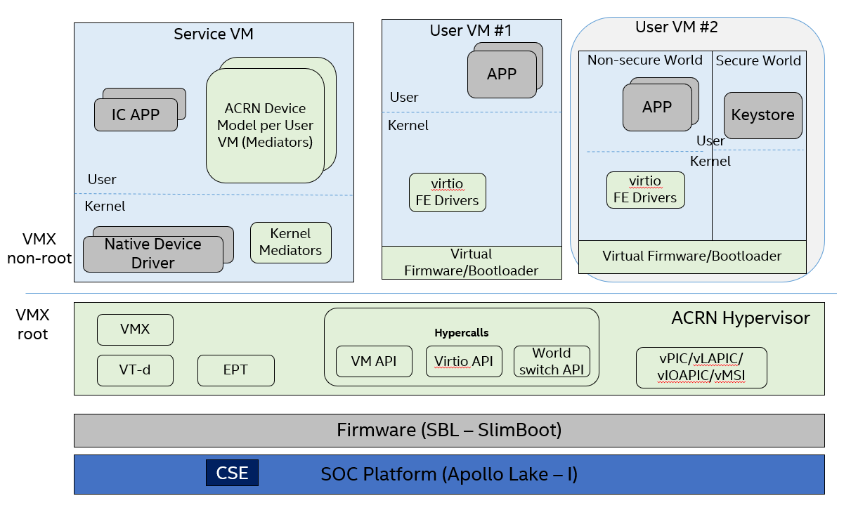
Figure 275 ACRN Hypervisor Overview
This document focuses only on the security part of the automotive system built on top of the ACRN hypervisor. This includes how to build a secure system as well as how to virtualize the security features that the system can provide.
Usages
As shown in Figure 276, the ACRN hypervisor can be used to build a Software Defined Cockpit (SDC) or an In-Vehicle Experience (IVE) Solution that consolidates multiple VMs together on a single Intel SoC in-vehicle platform.
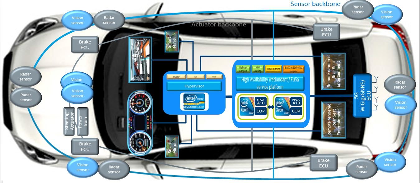
Figure 276 SDC and IVE system In-Vehicle
In this system, the ACRN hypervisor is running at the most privileged level, VMX root mode, in virtualization technology terms. The hypervisor has full control of platform resources, including the processor, memory, devices, and in some cases, secrets of the guest OS. The ACRN hypervisor supports multiple guest VMs running in parallel in the less privileged level called VMX non-root mode.
The Service VM is a special VM. While it runs as a guest VM in VMX non-root mode, it behaves as a privileged guest VM controlling the behavior of other guest VMs. The Service VM can create a guest VM, suspend and resume a guest VM, and provide device mediation services (Device Models) for other guest VMs it creates.
In an SDC system, the Service VM also contains safety-critical IC (Instrument Cluster) applications. ACRN is designed to make sure the IC applications are well isolated from other applications in the Service VM such as Device Models (Mediators). A crash in other guest VM systems must not impact the IC applications, and must not cause any DoS (Deny of Service) attacks. Functional safety is out of scope of this document.
In Figure 275, the other guest VMs are referred to as User VM. These other VMs provide infotainment services (such as navigation, music, and FM/AM radio) for the front seat or rear seat.
The User VM systems can be based on Linux (LaaG, Linux as a Guest) or Android* (AaaG, Android as a Guest) depending on the customer’s needs and board configuration. It can also be a mix of Linux and Android systems.
In each User VM, a “side-car” OS system can accompany the normal OS system. We call these two OS systems “secure world” and “non-secure world”, and they are isolated from each other by the hypervisor. Secure world has a higher “privilege level” than non-secure world; for example, the secure world can access the non-secure world’s physical memory but not vice-versa. This document discusses how this security works and why it is required.
Careful consideration should be made when evaluating using the Service VM as the Trusted Computing Base (TCB). The Service OS may be a fairly large system running many lines of code; thus, treating it as a TCB doesn’t make sense from a security perspective. To achieve the design purpose of “defense in depth”, system security designers should always ask themselves, “What if the Service VM is compromised?” and “What’s the impact if this happens?” This HLD document discusses how to security-harden the Service VM system and mitigate attacks on the Service VM.
ACRN High-Level Security Architecture
This chapter provides a high-level architecture design overview of ACRN security features and their development.
Secure / Verified Boot
The security of the entire system built on top of the ACRN hypervisor depends on the security from platform boot to User VM launching. Each layer or module must verify the security of the next layer or module before transferring control to it. Verification can be checking a cryptographic signature on the executable of the next step before it is launched.
Note that measured boot (as described well in this boot security technologies document) is not currently supported for ACRN and its guest VMs.
Boot Flow
ACRN supports two verified boot sequences.
1) Verified Boot Sequence with SBL
As shown in Figure 277, the Converged Security Engine Firmware (CSE FW) behaves as the root of trust in this platform boot flow. It authenticates and starts the BIOS (SBL), whereupon the SBL is responsible for authenticating and verifying the ACRN hypervisor image. Currently the Service VM kernel is built together with the ACRN hypervisor as one image bundle, so this whole image signature is verified by SBL before launching.
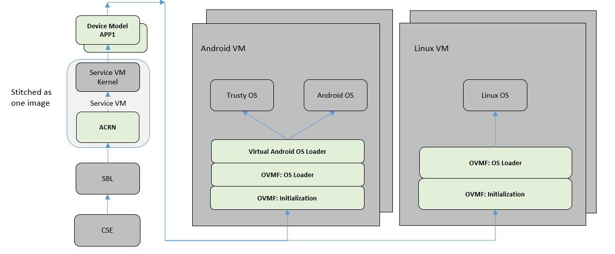
Figure 277 ACRN Boot Flow with SBL
2) Verified Boot Sequence with UEFI
As shown in Figure 278, in this boot sequence,UEFI authenticates and starts the ACRN hypervisor firstly,and hypervisor will return to UEFI environment to authenticate and load Service VM kernel bootloader.
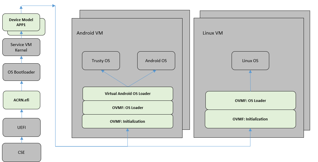
Figure 278 ACRN Boot Flow with UEFI
As long as the Service VM kernel starts, the Service VM kernel will load all its subsystems subsequently. In order to launch a User VM, a DM process is started to launch the virtual BIOS (OVMF), and eventually, the OVMF is responsible for verifying and launching the User VM kernel (or the Android OS loader for an Android User VM).
Secure Boot
In the entire boot flow, the chain of trust must be unbroken. This is achieved by the secure boot mechanism. Each module in the boot flow must authenticate and verify the next module by using a cryptographic digital signature algorithm.
The well-known image signing algorithm uses cryptographic hashing and public key cryptography with PKCS1.5 padding.
The 2018 minimal requirements for cryptographic strength currently are:
- SHA256 for image cryptographic hashing.
- RSA2048 for cryptographic digital signature signing and verification.
We strongly recommend that SHA512 and RSA3072+ be used for a product shipped in 2018, especially for a product which has a long production life such as an automotive vehicle.
The CSE FW image is signed with an Intel RSA private key. All other images should be signed by the responsible OEM. Our customers and partners are responsible for image signing, ensuring the key strength meets security requirements, and storing the secret RSA private key securely.
Guest Secure Boot with OVMF
Open Virtual Machine Firmware (OVMF) is an EDK II based project to enable UEFI support for virtual machines in a virtualized environment. In ACRN, OVMF is deployed to launch a User VM, as if the User VM is booted on a machine with UEFI firmware.
UEFI Secure Boot defines how a platform’s firmware can authenticate a digitally signed UEFI image, such as an operating system loader or a UEFI driver stored in an option ROM. This provides the capability to ensure that those UEFI images are only loaded in an owner-authorized fashion and provides a common means to ensure platform’s security and integrity over systems running UEFI-based firmware. UEFI Secure Boot is already supported by OVMF.
Figure 279 shows a Secure Boot overview in UEFI.
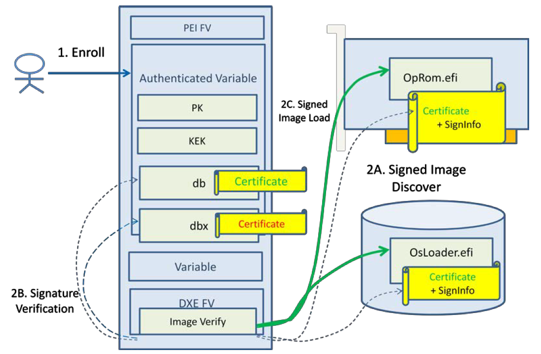
Figure 279 UEFI Secure Boot Overview
UEFI Secure Boot is controlled by a set of UEFI Authenticated Variables which specify the UEFI Secure Boot Policy; the platform manufacturer or the platform owner enroll the policy objects, which includes the n-tuple of keys {PK, KEK, db,dbx} as step 1. During each successive boot, the UEFI secure boot implementation will assess the policy in order to verify the signed images that are discovered in a host-bus adapter or on a disk. If the images pass policy, then they are invoked.
UEFI Secure Boot implementations use these keys:
- Platform Key (PK) is the top-level key in Secure Boot; UEFI supports a single PK, which is generally provided by the manufacturer.
- Key Exchange Key (KEK) is used to sign Signature and Forbidden Signature Database updates.
- Signature Database (db) contains kyes and/or hashes of allowed EFI binaries.
And keys and certificates are in multiple format:
- .key PEM format private keys for EFI binary and EFI signature list signing.
- .crt PEM format certificates for sbsign.
- .cer DER format certificates for firmware.
In ACRN, User VM Secure Boot can be enabled by below steps.
- Generate keys(PK/KEK/DB) with key generation tool such as Ubuntu KeyGeneration, PK.der, KEK.der and db.der will be enrolled in UEFI BIOS, db.key and db.crt will be used to sign user VM bootloader/kernel.
- Create a virtual disk to hold PK.der, KEK.der and db.der, then launch the User VM with this virtual disk which contains the keys for enrollment.
- Start the OVMF in writeback mode to ensure the keys are persistently stored in the OVMF image.
- Enroll keys in OVMF GUI by following the Secure Boot configuration flow and enable secure boot mode.
- Perform writeback via reset in OVMF.
- Sign user VM images with db.key and db.crt.
- Boot user VM with Secure Boot enabled.
Service VM Hardening
In the ACRN project, the reference Service VM is based on the Clear Linux OS. Customers may choose to use different open source OSes or their own proprietary OS systems. To minimize the attack surfaces and achieve the goal of “defense in depth”, there are many common guidelines to ensure the security of Service VM system.
As shown in Figure 277 and Figure 278 above, the integrity of the User VM depends on the integrity of the DM module and vBIOS/vOSloader in the Service VM. Hence, Service VM integrity is critical to the entire User VM security. If the Service VM system is compromised, all the other User VMs may be jeopardized.
In practice, the Service VM designer and implementer should obey at least the following rules:
- Verify that the Service VM is a closed system and doesn’t allow the user to install any unauthorized 3rd-party software or components.
- Verify that external peripherals are constrained.
- Enable kernel-based hardening techniques, for example dm-verity (to ensure integrity of the DM and vBIOS/vOSloaders), and kernel module signing.
- Enable system level hardening such as MAC (Mandatory Access Control).
Detailed configurations and policies are out of scope for this document. For good references on OS system security hardening and enhancement, see AGL security and Android security
Hypervisor Security Enhancement
This section describes the ACRN hypervisor security enhancement for memory boundary access and interfaces between VMs and the hypervisor, such as Hypercall APIs, I/O emulations, and EPT violation handling.
The main security goal of the ACRN hypervisor design is to prevent Privilege Escalation and enforce Isolation, for example:
- VMM privilege escalation (VMX non-root -> VMX root)
- Non-secure OS software (running in AaaG) accessing secure world TEE assets
- Unauthorized software from executing in the hypervisor
- Cross-guest VM attacks
- Hypervisor secret information leakage
Memory Management Enhancement
Background
The ACRN hypervisor has ultimate access control of all the platform memory spaces (see Memory Management high-level design). Note that on the APL platform, SGX and TME are not currently supported.
The hypervisor can read and write any physical memory space allocated to any guest VM, and can even fetch instructions and execute the code in the memory space from any guest VM. If the hypervisor has MMU misconfiguration or is compromised by an attacker, it must be constrained in some manner to prevent the hypervisor from accessing guest memory space either maliciously or accidentally. As a best security practice, any memory content from a guest VM memory space must not be trusted by the hypervisor. In other words, there must be a trust boundary for memory space between the hypervisor and Guest VMs.
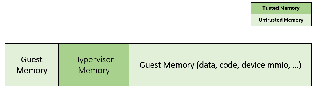
Figure 280 Hypervisor and Guest Memory Layout
The hypervisor must appropriately configure the EPT tables to disallow any guest to access (read/write/execution) the memory space owned by the hypervisor.
Memory Access Restrictions
The fundamental rules of restricting hypervisor memory access are:
- By default, prohibit any access to all guest VM memory. This means that when the hypervisor initially sets up its own MMU paging tables (HVA->HPA mapping), it only grants permissions for hypervisor memory space (excluding guest VM memory)
- Grant access permission for the hypervisor to read/write a specific guest VM memory region on demand. The hypervisor must never grant execution permission for itself to fetch any code instructions from guest memory space because there is no reason to do that.
In addition to these rules, the hypervisor must also implement generic best-practice memory configurations for access to its own memory in host CR3 MMU paging tables, such as splitting hypervisor code and data (stack/heap) sections, and then applying W ⊕ X policy, which means if memory is Writable, then the hypervisor must make it non-eXecutable. The hypervisor must configure its code as read-only and executable, and configure its data as read-write. Optionally, if there are read-only data sections, it would be best if the hypervisor configures them as read-only.
The following sections focus on the rules mentioned above for memory access restriction on guest VM memory (not restrictions on the hypervisor’s own memory access).
SMAP/SMEP Enablement in the Hypervisor
For the hypervisor to isolate access to the guest VM memory space, three typical solutions exist:
Configure the hypervisor/VMM MMU CR3 paging tables by removing the execution permission (setting NX bit) or removing mapping completely (setting not-present) for the guest memory space.
In practice, this works very well for NX setting to disable instruction fetching from any guest memory space. However, it is not suitable for read/write access isolation. For example, if the hypervisor removes the mapping to a guest memory page in host CR3 paging tables, when the hypervisor wants to access that specific guest memory page, the hypervisor must first add mapping back to its CR3 paging tables before accessing that page, and revert the mapping after accessing.
This remapping causes code complexity and a performance penalty and may even require the hypervisor to flush the TLB. This solution won’t be used by the ACRN hypervisor.
Use CR0.WP (write-protection) bit.
This processor feature allows pages to be protected from supervisor-mode write access. If the host/VMM CR0.WP = 0, supervisor-mode write access is allowed to linear addresses with read-only access rights. If CR0.WP = 1, they are not allowed. User-mode write access is never allowed for linear addresses with read-only access rights, regardless of the value of CR0.WP.
To implement this WP protection, the hypervisor must first configure all the guest memory space as “user-mode” accessible memory, and as read-only access. In other words, the corresponding paging table entry U/S bit and R/W bit must be set in host CR3 paging tables for all those guest memory pages.
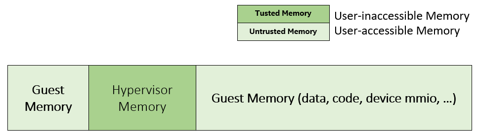
Figure 281 Configure Guest Memory as User-accessible
This setting seems meaningless since all the code in the ACRN hypervisor is running in Ring 0 (supervisor-mode), and no code in the hypervisor will be executed in Ring 3 (no user-mode applications in the hypervisor / vmx-root).
However, these settings are made in order to make use of the CR0.WP protection capability, because if CR0.WP = 1, if the hypervisor code is running in Ring 0 and maliciously attempts to write a user-accessible read-only memory page (in guest memory space), then this malicious behavior can be thwarted with a page fault (#PF) by the processor in the hypervisor. Whenever the hypervisor has a valid reason to have a write access to user-accessible read-only memory (guest memory), it can disable CR0.WP (clear CR0.WP) before writing, and afterwards set CR0.WP back to 1.
This solution is better than the 1st solution above because it doesn’t need to change the host CR3 paging tables to map or unmap guest memory pages and doesn’t need to flush the TLB. However, it cannot prevent the hypervisor (running in Ring 0 mode) from reading guest memory space because this CR0.WP bit doesn’t control read access behaviors. This read access protection is essentially required because sometimes there may be secrets in guest memory and if the hypervisor can be hacked to read those memory contents, then it may cause secret leaking to attackers.
Use processor SMEP and SMAP capabilities.
This solution is a best solution because SMAP can prevent the hypervisor from both reading and writing guest memory, and SMEP can prevent the hypervisor from fetching/executing code in guest memory. This solution also has minimal performance impact; like the CR0.WP protection, it doesn’t require TLB flush (incurring a performance penalty) and has less code complexity.
The following sections will focus on this SMEP/SMAP protection. SMEP and SMAP are widely used by all modern Operating System software such as Windows and Linux, for isolating kernel and user memory, and can mitigate many vulnerability exploits.
Guest Memory Execution Prevention
SMEP is designed to prevent user memory malicious code (typically attacker-supplied) from being executed in the kernel (Ring 0) privilege level. As long as the CR4.SMEP = 1, software operating in supervisor mode cannot fetch instructions from linear addresses that are accessible in user mode.
In the ACRN hypervisor, the attacker-supplied memory could be any guest memory, because the hypervisor doesn’t trust all the data/code from guest memory by design.
In order to activate SMEP protection, the ACRN hypervisor must:
- Configure all the guest memory as user-accessible memory (U/S = 1). No matter what settings for NX bit and R/W bit in corresponding host CR3 paging tables.
- Set CR4.SMEP bit. In the entire lifecycle of the hypervisor, this bit value always remains one.
As an alternative, NX feature is used for this purpose by setting the corresponding NX (non-execution) bit for all the guest memory mapping in host CR3 paging tables.
Since the hypervisor code never runs in Ring 3 mode, either of these two solutions works very well. Both solutions are enabled in the ACRN hypervisor.
Guest Memory Access Prevention
Supervisor Mode Access Prevention (SMAP) is yet another powerful processor feature which makes it harder for malicious programs to “trick” the kernel into using instructions or data from a user-space application program.
This feature is controlled by the CR4.SMAP bit. When that bit is set, any attempt to access user-accessible memory pages while running in a privileged or kernel mode will lead to a page fault.
However, there are times when the kernel legitimately needs to work with user-accessible memory pages. The Intel processor defines a separate “AC” flag (in RFLAGS register) that control the SMAP feature. If the AC flag is clear, SMAP protection is in force when CR4.SMAP=1; otherwise access to user-accessible memory pages is allowed even if CR4.SMAP=1. The “AC” flag provides suppression for SMAP enforcement.
To manipulate that flag relatively quickly, STAC (set AC flag) and CLAC (clear AC flag) instructions are introduced for this purpose. Note that STAC and CLAC can only be executed in kernel mode (CPL=0).
To activate SMAP protection in the ACRN hypervisor:
- Configure all the guest memory as user-writable memory (U/S bit = 1, and R/W bit = 1) in corresponding host CR3 paging table entries, as shown in Figure 282 below.
- Set CR4.SMAP bit. In the entire lifecycle of the hypervisor, this bit value always remains one.
- When needed, use STAC instruction to suppress SMAP protection, and use CLAC instruction to restore SMAP protection.
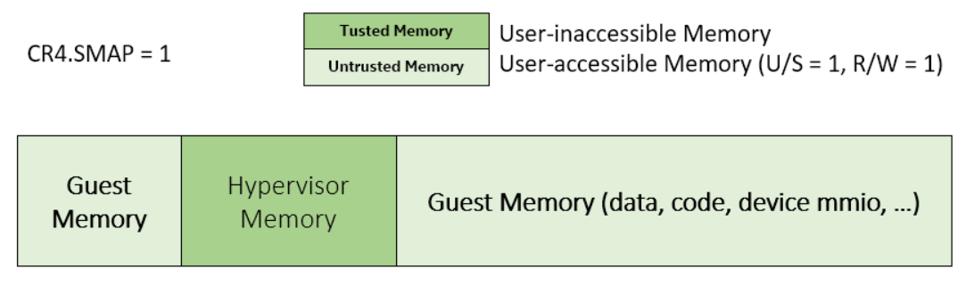
Figure 282 Setting SMAP and Configuring U/S=1, R/W=1 for All Guest Memory Pages
For example, Figure 282 shows a module of the hypervisor code (running in Ring 0 mode) attempting to perform a legitimate read (or write) access to a data area in guest memory page.
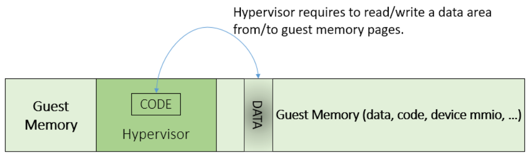
Figure 283 Hypervisor Access to Guest Memory
The hypervisor can do these steps:
- Execute STAC instruction to suppress SMAP protection;
- Perform read/write access on guest DATA area.
- Execute CLAC instruction to restore SMAP protection.
The attack surface can be minimized because there is only a very small window between step 1 and step 3 in which the guest memory can be accessed by hypervisor code running in ring 0.
Rules to Access Guest Memory in the Hypervisor
In the ACRN hypervisor, functions stac() and clac() wrap
STAC and CLAC instructions respectively, and functions
copy_to_gpa(), and copy_from_gpa() can be used to copy
an arbitrary amount of data to or from VM memory area.
Whenever the hypervisor needs to perform legitimate read/write access to guest memory pages, one of functions above must be used. Otherwise, the #PF will be triggered by the processor to prevent malicious or unintended access from/to the guest memory pages.
These functions must also internally check the address availabilities, for example, ensuring the input address accessed by the hypervisor must have a valid mapping (GVA->GPA mapping, GPA->HPA EPT mapping and HVA->HPA host MMU mapping), and must not be in the range of the hypervisor memory. Details of these ordinary checks are out of scope in this document.
Avoidance of Memory Information Leakage
Protecting the hypervisor’s memory is critical to the security of the entire platform. The hypervisor must prevent any memory content (e.g. stack or heap) from leaking to guest VMs. Some of the hypervisor memory content may contain platform secrets such as SEEDs, which are used as the root key for its guest VMs. Xen Advisories have many examples of past hypervisor memory leaks, ACRN developers can refer to this link to understand how to avoid this in coding.
Memory content from one guest VM might be leaked to another guest VM. So in ACRN and Device Model design, when one guest VM is destroyed or crashes, its memory content should be scrubbed either by the hypervisor or the Service VM device model process, in case its memory content is re-allocated to another guest VM which could otherwise leave the previous guest VM secrets in memory.
Secure Hypervisor Interface
Hypercall API Interface Hardening
The hypercall API is the primary interface between a guest VM and the hypervisor.
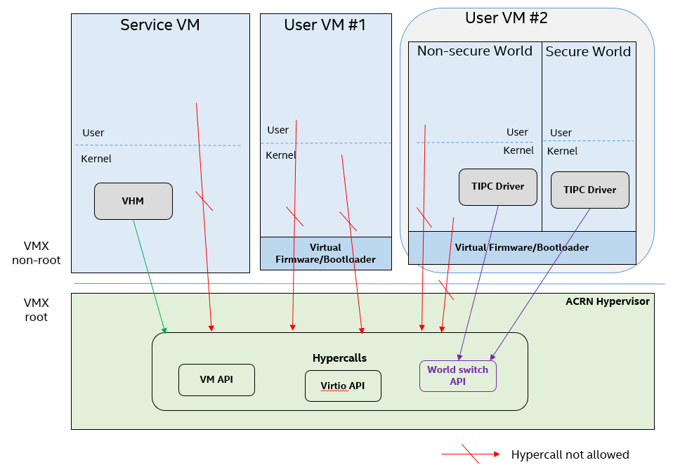
Figure 284 Hypercall Interface Restriction
As shown in Figure 284, there are some restrictions for hypercall invocation in the hypervisor design:
- Hypercalls from ring 1~3 of any guest VM are not allowed. The hypervisor must discard such hypercalls silently. Only ring-0 hypercalls from the guest VM are handled by the hypervisor.
- All the hypercalls (except world_switch hypercall) must be called from the ring-0 driver of the Service VM. World_switch Hypercall is used by the TIPC (Trusty IPC) driver to switch guest VM context between secure world and non-secure world. Further details will be discussed in the Secure Isolated World (Trusty) section.
- For those hypercalls that may result in data inconsistent intra hypervisor
when they are executed concurrently, such as
hcall_create_vm()hcll_destroy_vm()etc. spinlock is used to ensure these hypercalls are processed in the hypervisor in a serializing way.
In addition to the above rules, there are other regular checks in the hypercall implementation to prevent hypercalls from being misused. For example, all the parameters must be sanitized, unexpected hypervisor memory overwrite must be avoided, any hypervisor memory content/secrets must not be leaked to guest, and any memory/code injection must be eliminated.
I/O Emulation Handler
I/O port monitoring is also widely used by the ACRN hypervisor to emulate legacy I/O access behaviors.
Typically, the I/O instructions could be IN, INS/INSB/INSW/INSD, OUT, OUTS/OUTSB/OUTSW/OUTSD with arbitrary port (although not all the I/O ports are monitored by the hypervisor). As with other interface (e.g. hypercalls), the hypervisor performs security checks for all the I/O access parameters to make sure the emulation behaviors are correct.
EPT Violation Handler
The Extended Page Table (EPT) is typically used by the hypervisor to monitor MMIO (or other types of ordinary memory access) operation from guest VM. The hypervisor then emulates the MMIO instructions with design behaviors.
As done for I/O emulation, this interface could also be manipulated by malicious software in guest VM to compromise system security.
Other VMEXIT Handlers
There are some other VMEXIT handlers in the hypervisor which might take untrusted parameters and registers from guest VM, for example, MSR write VMEXIT, APIC VMEXIT.
Sanity checks are performed by the hypervisor to avoid security issue when handling those special VMEXIT.
Guest Instruction Emulation
Instruction emulation implemented by the hypervisor must also be checked securely. Emulating x86 instruction is complicated, and there are many known security CVEs reported by attackers in the KVM/XEN/QEMU community. This is a “hotspot” where the hypervisor may potentially have vulnerability bugs.
Security validation process and secure code review must ensure all the instruction emulations behave as defined in the IA32 SDM document.
Virtual Power Life Cycle Management
In a virtualization environment, each User VM can have its virtual power managed just like native behavior. For example, if a User VM is required to enter S3 (Suspend to RAM) for power consumption saving, then the hypervisor and DM processor in Service must handle it correctly. Similarly, virtual cold/warm reboot is also supported. How to implement virtual power life cycle management is out of scope in this document.
This subsection is intended to describe the security issues for those power cycles.
User VM Power On and Shutdown
The memory of the User VM is allocated dynamically by the DM process in the Service VM before the User VM is launched. When the User VM is shutdown (or crashed), its memory will be freed to Service VM memory space. Later on, if there is a new User VM launch event occurring, DM may potentially allocate the same memory content (or some overlaps) for this new User VM.
In the virtualization environment, a security goal is to ensure User VM isolation, not only for runtime memory isolation (e.g. w/ EPT), but also for data at rest isolation.
Under this situation, if the memory contents of a previous User VM is not scrubbed by either DM or the hypervisor, then the new launched User VM could access the previous User VM’s secrets by scanning the memory regions allocated for the new User VM.
In ACRN, the memory content is scrubbed in Device Model after the guest VM is shutdown.
User VM Reboot
The behaviors of cold boot of virtual User VM reboot is the same as that of previous virtual power-on and shutdown events. There is a special case: virtual warm reboot.
When a User VM encounters a panic, its kernel may trigger a warm reboot, so that in the next power cycle, a special purpose-built OS image is launched to dump the memory content for debugging analysis. In a warm reboot, the memory content must be preserved after a virtual power cycle. However, this violates the security rules above.
This typically is fine in project ACRN, because in the next virtual power cycle, the same memory content won’t be re-allocated to another User VM.
But there is a new issue when secure world (TEE/Trusty) is considered, because the memory content of secure world must not be dumped by a non-secure world User VM. More details will be discussed in the section on Platform Root of Trust Key/SEED Derivation.
Normally, this warm reboot (crashdump) feature is a debug feature, and must be disabled in a production release. User who wants to use this feature must possess the private signing key to re-sign the image after enabling the configuration.
User VM Suspend/Resume
There is no special design considerations for normal User VM without secure world supported, as long as the EPT/VT-d memory protection/isolation is active during the entire suspended time.
Secure world (Trusty/TEE) is a special case for virtual suspend. Unlike the non-secure world of User VM, whose memory content can be read/written by Service VM, the memory content of secure world of User VM must not be visible to Service VM. This is designed for security with defense in depth.
During the entire process of User VM sleep/suspend, the memory protection for secure-world is preserved too.The physical memory region of secure world is removed from EPT paging tables of any guest VM, even including the Service VM.
Third-party libraries
All the third-party libraries must be examined before use to verify there are no known vulnerabilities in the library source code. Typically, the CVE site https://cve.mitre.org/cve/search_cve_list.html can be used to search for known vulnerabilities.
Platform Root of Trust Key/SEED Derivation
For security reason, each guest VM requires a root key, which is used to derive many other individual keys for different purposes, for example, secure storage encryption, keystore master key, and HMAC keys.
In the APL platform, CSE FW will generate platform SEED (pSEED, 256bit) unique per device since it is derived from a unique chipset secret burned into the chip.
Then on each boot, the SBL BIOS is responsible for retrieving the pSEED from CSE FW, and deriving two other derivatives (dSEED, and uSEED).
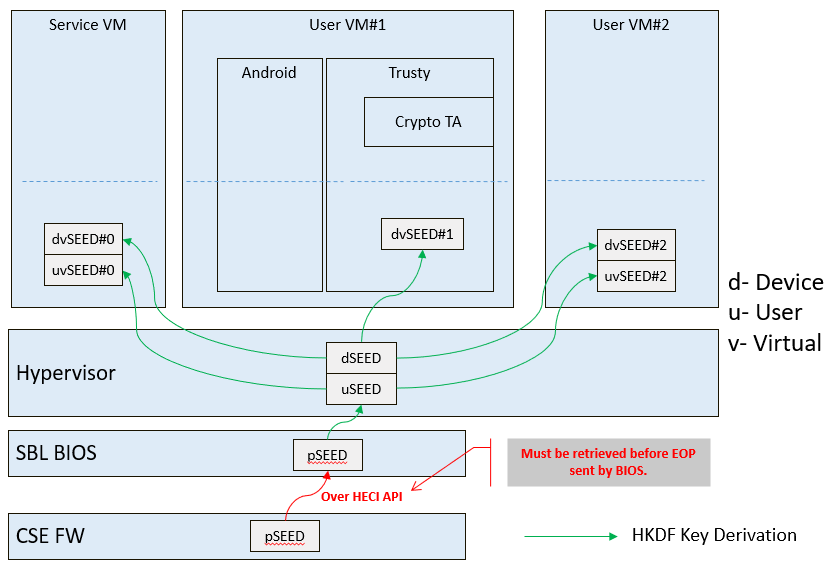
Figure 285 Platform SEED (pSEED) Derivation
As shown in Figure 285 above, the hypervisor then derives multiple child SEEDs for multiple guest VMs. A guest VM must not be able to know the SEEDs of any other guest VMs.
The algorithm used in the hypervisor to derive keys is HKDF (HMAC-based Extract-and-Expand Key Derivation Function, RFC5869. The crypto library mbedtls has been chosen for project ACRN.
The parameters of HDKF derivation in the hypervisor are:
VMInfo= vm-uuid (from the hypervisor configuration file)
theHash=SHA-256
OutSeedLen = 64 in bytes
Guest Dev and User SEED (dvSEED/uvSEED)
dvSEED = HKDF(theHash, nil, dSEEd, VMInfo|”devseed”, OutSeedLen)
uvSEED = HKDF(theHash, nil, uSEEd, VMInfo|”userseed”, OutSeedLen
Secure Isolated World (Trusty)
This section explains how to build a secure isolated world in a specific guest VM such as the Android User VM. (See Trusty TEE for more information.)
On the APL platform, the secure world is used to run a virtualization-based Trusty TEE in an isolated world which serves Android as a guest (AaaG,) to get Google’s Android relevant certificates by fulfilling Android CDD requirements. Also as a plan, Trusty will be supported to provide security services for LaaG User VM as well.
Refer to this Google website for Trusty details and for Android CCD documents.
Secure World Architecture Design
To support a VT-TEE (Virtualization Technology based TEE) Trusty on ACRN, the hypervisor creates an isolated secure world in a User VM.
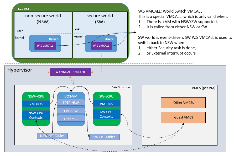
Figure 286 Secure World
In Figure 286, the Trusty OS runs in the User VM secure world and a Linux- or Android-based User VM runs in the non-secure world.
By design, the secure world is able to read and write to all non-secure world’s memory space. But non-secure world applications cannot have access to secure world’s memory. This is guaranteed by switching different EPT tables when a world switch (WS) hypercall is invoked. The WS Hypercall can have parameters to specify the services cmd ID requested from non-secure world.
To design the “one VM, two worlds” architecture, there is a single User VM structure per-User VM in the hypervisor, but two vCPU structures that save non-secure/secure world virtual logical processor states respectively.
Whenever there is a WS hypercall from non-secure world, the hypervisor will copy non-secure world CPU contexts from Guest VMCS to non-secure world-vCPU structure for saving contexts, and then copy secure-world CPU contexts from secure-world-vCPU structure to Guest VMCS, then do VMRESUME to secure-world, and vice versa. The EPTP pointer will also be updated accordingly in VMCS (not shown in Figure 286).
Trusty (Secure World) Memory Mapping View
As per the secure world design, Trusty can have read/write access to non-secure world’s memory, but non-secure world cannot access Trusty secure world’s memory. In the hypervisor EPT configuration shown in Figure 287 below, the secure world EPTP page table hierarchy must contain non-secure world address space, while Trusty world’s address space must be removed from the non-secure world EPTP page table hierarchy.
Since there is no need to allow Trusty to execute memory from non-secure world, for security reason, the execution (X) permission must be removed for non-secure world address space in secure world EPT table configuration.
To save page tables and share the mappings for non-secure world address space, the hypervisor relocates the Secure World’s GPA to a very high position: 511G-512G. Hence, the PML4 for Trusty World are separated from non-secure World. PDPT/PD/PT for low memory (<511G) are shared in both Trusty World’s EPT and non-secure World’s EPT. PDPT/PD/PT for high memory (>=511G) are valid for Trusty World’s EPT only.
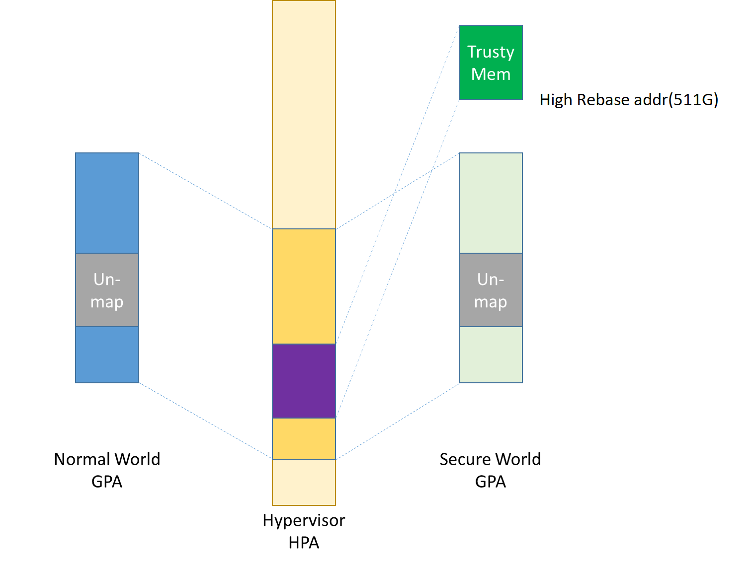
Figure 287 Memory View for User VM non-secure World and Secure World
Trusty/TEE Hypercalls
Two hypercalls are introduced to assist in secure world (Trusty/TEE) execution on top of the hypervisor.
Hypercall - Trusty Initialization
When a User VM is created by the DM in the Service VM, if this User VM supports a secure isolated world, then this hypercall will be invoked by OSLoader(it could be Android OS loader in Figure 277 and Figure 278 above) to create / initialize the secure world (Trusty/TEE).
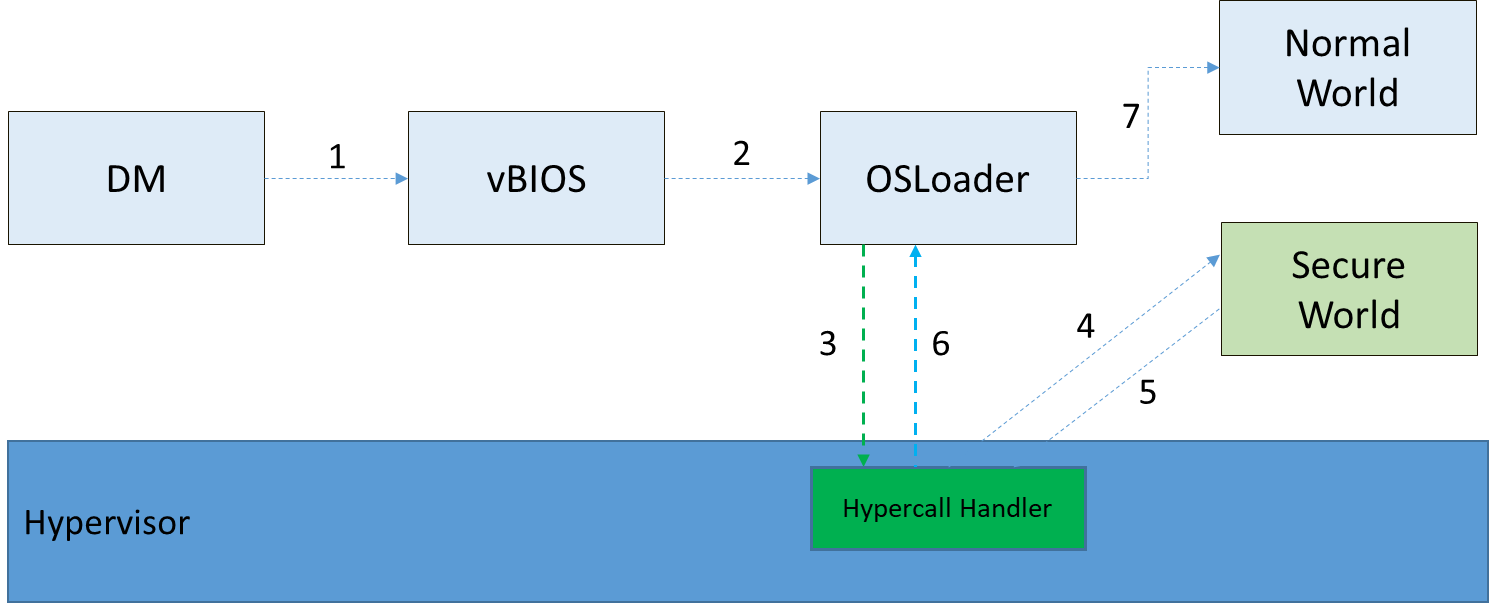
Figure 288 Secure World Start Flow
In Figure 288 above, the OSLoader is responsible for loading TEE/Trusty image to a dedicated and reserved memory region, and locating its entry point of TEE/Trusty executable, then executes a hypercall which exits to the hypervisor handler.
In the hypervisor, from a security perspective, it removes GPA->HPA mapping of secure world from EPT paging tables of both User VM non-secure world and even Service VM. This is intended to disallow non-secure world and Service VM to access the memory region of secure world for security reasons as previously mentioned
After all is set up by the hypervisor, including vCPU context initialization, the hypervisor eventually does vmresume (step 4 in Figure 288 above) to the entry point of secure world TEE/Trusty, then Trusty OS gets started in vmx non-root mode to initialize itself, and loads its TAs (Trusted Applications) so that the security services can be ready right before non-secure OS gets started.
After Trusty OS completes its initialization, a world switching (WS, see subsection below) hypercall is invoked (step 5 in Figure 288 above), and then the hypervisor takes control back, and resumes to the OSLoader (step 6 in Figure 288 above) for continuing execution in guest VM non-secure world context.
Note that this trusty initialization hypercall can only be called once in the User VM life cycle.
Hypercall - Trusty Switching
There is another special hypercall introduced only for world switching between non-secure world and secure world in a User VM.
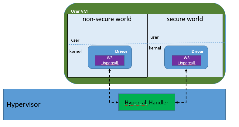
Figure 289 World Switching Hypercall
Whenever this hypercall is invoked in User VM, the hypervisor will unconditionally switch to the other world. For example, if it is called in non-secure world, the hypervisor will then switch context to secure world. After secure world completes its security tasks (or an external interrupt occurs), this hypercall will be called again, then the hypervisor will switch context back to non-secure world.
During entire world switching process, Service VM is not involved. This hypervisor is only available to a User VM with duo-worlds supported.
Secure Storage Virtualization
Secure storage is one of the security services provided by secure world (TEE/Trusty). In the current implementation, secure storage is built up on the RPMB partition in eMMC (or UFS, and NVMe storage). Details of how RPMB works are out of scope for this document.
Since currently the eMMC in APL SoC platform only has a single RPMB partition for tamper-resistant and anti-replay secure storage, the secure storage (RPMB) should be virtualized in order to support multiple guest User VMs. However, although future generation of flash storage (e.g. UFS 3.0, and NVMe) supports multiple RPMB partitions, this document still only focuses on the virtualization solution for single-RPMB flash storage device in APL SoC platform.
The following Figure 290 illustrates the virtualization of secure storage high-level architecture overview.
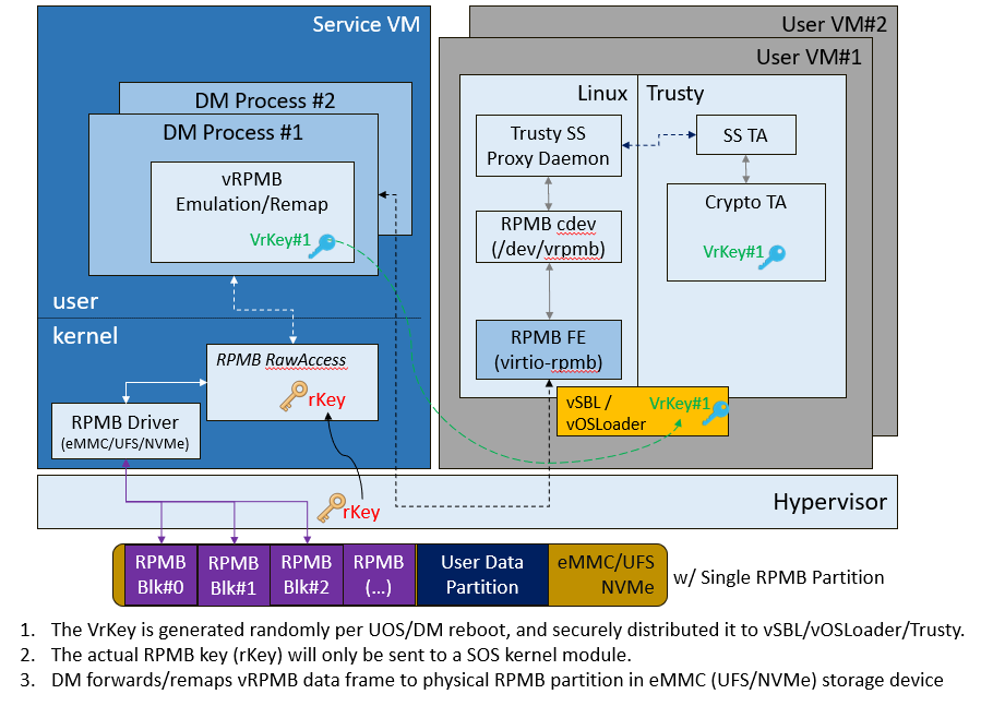
Figure 290 Secure Storage Virtualization
In Figure 290, the rKey is the physical RPMB authentication key used for data authenticated read/write access between the Service VM kernel and the physical RPMB controller in eMMC device. The VrKey is the virtual RPMB authentication key used for authentication between the DM module in Service VM and its corresponding User VM secure software. Each User VM (if secure storage is supported) has its own VrKey, generated randomly when DM process starts, and is securely distributed to User VM secure world for each reboot. The rKey is fixed on a specific platform unless the eMMC is replaced with another one.
The details of physical RPMB key (rKey) provision are out of scope. In the current project ACRN on APL platform, the rKey is provisioned by BIOS (SBL) right after production device ends its manufacturing process.
For each reboot, the BIOS/SBL always retrieves the rKey from CSE FW (or generated from a special SEED that is retrieved from CSE FW, refer to Platform Root of Trust Key/SEED Derivation). The SBL hands this over to the ACRN hypervisor, and the hypervisor in turn sends it to the Service VM kernel.
As an example, secure storage virtualization workflow for data write access is like this:
- User VM Secure world (e.g. Trusty) packs the encrypted data and signs it with the vRPMB authentication key (VrKey), and sends the data along with its signature over the RPMB FE driver in User VM non-secure world.
- After DM process in Service VM receives the data and signature, then the vRPMB module in DM verifies them with the shared secret (vRPMB authentication key, VrKey),
- If verification is successful, the vRPMB module does data address remap (remembering that the multiple User VMs share a single physical RPMB partition), and forwards the data to the Service VM kernel. The kernel packs the data and signs it with the physical RPMB authentication key (rKey). Eventually, the data and its signature will be sent to physical eMMC device.
- If the verification is successful in eMMC RPMB controller, then the data will be written into storage device.
This work flow of authenticated data read is very similar to this flow above, but in reverse order.
Note that there are some security considerations in this design:
- The rKey protection is very critical in this system. If it is leaked, an attacker can overwrite the data on RPMB, which violates the “tamper-resistant & anti-replay” capability.
- Typically, the vRPMB module in DM process of Service VM system can filter data access, preventing one User VM to perform read/write access to the data from another User VM. If the vRPMB module in the DM process is compromised, one User VM may also change/overwrite the secure data of other User VM.
Keeping the Service VM system as secure as possible is a very important goal in the system security design, please follow the recommendations in Service VM Hardening.
SEED Derivation
Refer to the previous section: Platform Root of Trust Key/SEED Derivation.
Trusty/TEE S3 (Suspend To RAM)
Secure world S3 design is not yet finalized. However, there is a temporary solution as explained below to make it work on top of ACRN.
Two new hypercalls are introduced: one saves the secure world processor contexts/states; the other one restores the secure world processor contexts/states.
The save state hypercall is called only in secure world (Trusty/TEE OS) as long as the Trusty receives a signal when the entire system (actually the non-secure OS issues this power event) is about to enter S3. While the restore state hypercall is called only by vBIOS when User VM is ready to resume from suspend state.
For security design consideration of handling secure world S3, please read the previous section: User VM Suspend/Resume.
Platform Security Feature Virtualization and Enablement
This section talks about how the hypervisor enables host CPU features (e.g., SGX) and enables platform features (e.g., HECI), to allow guest VMs the ability to use those features.
TPM 2.0 Virtualization (vTPM)
On APL platform, Intel® PTT (Platform Trust Technology) implements TPM functionalities based on TCG TPM 2.0 industry standard specification. PTT exposes TPM hardware interface as CRB (Command Response Buffer) defined in the TCG TPM 2.0 spec.
However, in project ACRN, TPM virtualization doesn’t assume it is based on PTT or discrete TPM; both TPMs (2.0) are supported by design. Customers are free to use either PTT or discrete TPM (but not at the same time). PTT, however, is a built-in TPM2.0 implementation in Intel APL platform, and does not require extra BOM cost (unlike discrete TPM).
Note that the underlying CSE FW/HW implements PTT functionalities, however, this TPM2.0 feature does not rely on MEI/HECI virtualization.
Unlike regular hardware, implementation of virtualizing a TPM must address both security and Trust.
The goal of virtualization is to provide TPM functionality to each guest VM, such as:
- Allows programs to interact with a TPM in a virtual system the same way they interact with a TPM on the physical system;
- Each User VM gets its own unique, emulated, software TPM, for example, vPCR and vNVRAM.
- One to one mapping between running vTPM instances and logical vTPM in each VM
SGX Virtualization (vSGX)
Refer to SGX Virtualization