SR-IOV Virtualization
SR-IOV (Single Root Input/Output Virtualization) can isolate PCIe devices to improve performance that is similar to bare-metal levels. SR-IOV consists of two basic units: PF (Physical Function), which supports SR-IOV PCIe extended capability and manages entire physical devices; and VF (Virtual Function), a “lightweight” PCIe function which is a passthrough device for VMs.
For details, refer to Chapter 9 of PCI-SIG’s PCI Express Base SpecificationRevision 4.0, Version 1.0.
SR-IOV Architectural Overview
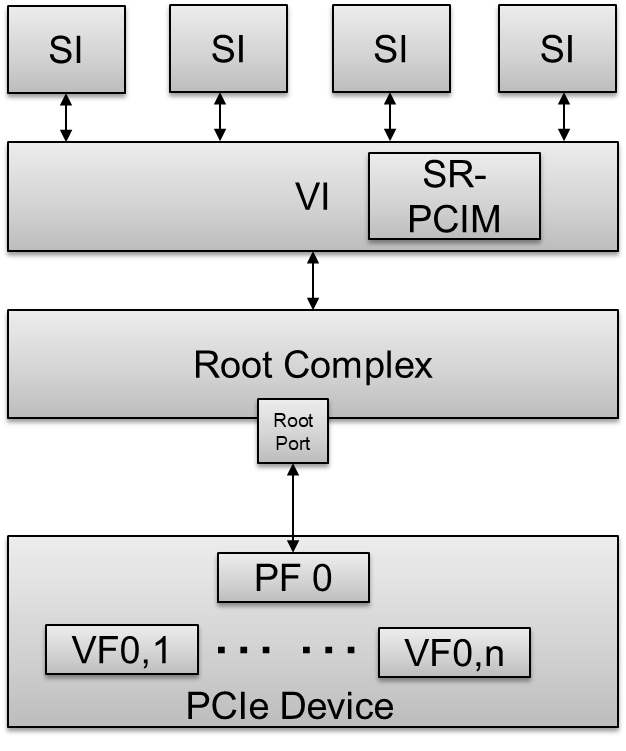
Figure 78 SR-IOV Architectural Overview
- SI - A System Image known as a VM.
- VI - A Virtualization Intermediary known as a hypervisor.
- SR-PCIM - A Single Root PCI Manager; it is a software entity for SR-IOV management.
- PF - A PCIe Function that supports the SR-IOV capability and is accessible to an SR-PCIM, a VI, or an SI.
- VF - A “light-weight” PCIe Function that is directly accessible by an SI.
SR-IOV Extended Capability
The SR-IOV Extended Capability defined here is a PCIe extended capability that must be implemented in each PF device that supports the SR-IOV feature. This capability is used to describe and control a PF’s SR-IOV Capabilities.
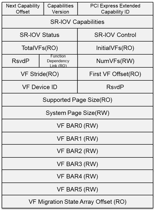
Figure 79 SR-IOV Extended Capability
- PCIe Extended Capability ID - 0010h.
- SR-IOV Capabilities - VF Migration-Capable and ARI-Capable.
- SR-IOV Control - Enable/Disable VFs; VF migration state query.
- SR-IOV Status - VF Migration Status.
- InitialVFs - Indicates to the SR-PCIM the number of VFs that are initially associated with the PF.
- TotalVFs - Indicates the maximum number of VFs that can be associated with the PF.
- NumVFs - Controls the number of VFs that are visible. NumVFs <= InitialVFs = TotalVFs.
- Function Link Dependency - The field used to describe dependencies between PFs. VF dependencies are the same as the dependencies of their associated PFs.
- First VF Offset - A constant that defines the Routing ID offset of the first VF that is associated with the PF that contains this Capability structure.
- VF Stride - Defines the Routing ID offset from one VF to the next one for all VFs associated with the PF that contains this Capability structure.
- VF Device ID - The field that contains the Device ID that should be presented for every VF to the SI.
- Supported Page Sizes - The field that indicates the page sizes supported by the PF.
- System Page Size - The field that defines the page size the system will use to map the VFs’ memory addresses. Software must set the value of the System Page Size to one of the page sizes set in the Supported Page Sizes field.
- VF BARs - Fields that must define the VF’s Base Address Registers (BARs). These fields behave as normal PCI BARs.
- VF Migration State Array Offset - Register that contains a PF BAR relative pointer to the VF Migration State Array.
- VF Migration State Array – Located using the VF Migration State Array Offset register of the SR-IOV Capability block.
For details, refer to the PCI Express Base Specification Revision 4.0, Version 1.0 Chapter 9.3.3.
SR-IOV Architecture In ACRN
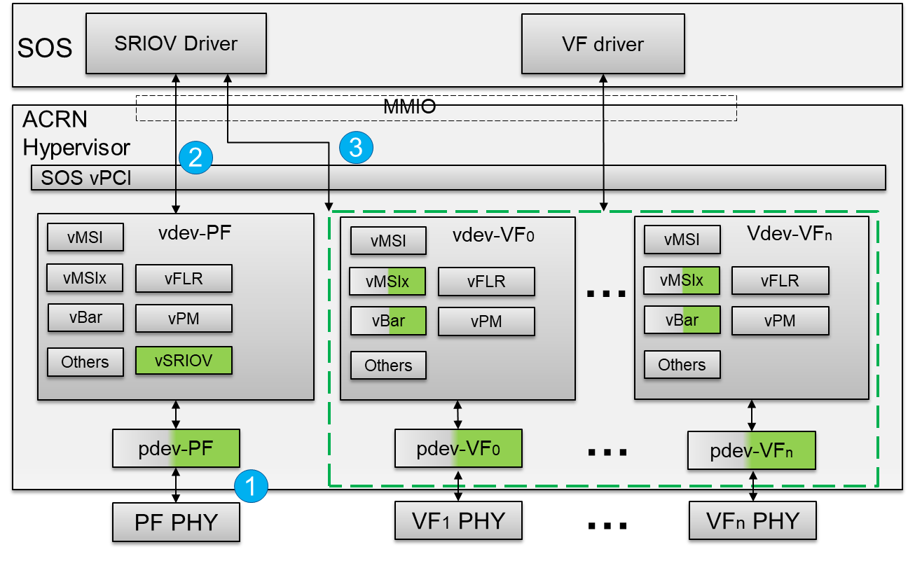
Figure 80 SR-IOV Architectural in ACRN
- A hypervisor detects a SR-IOV capable PCIe device in the physical PCI device enumeration phase.
- The hypervisor intercepts the PF’s SR-IOV capability and accesses whether to enable/disable VF devices based on the VF_ENABLE state. All read/write requests for a PF device passthrough to the PF physical device.
- The hypervisor waits for 100ms after VF_ENABLE is set and initializes VF devices. The differences between a normal passthrough device and SR-IOV VF device are physical device detection, BARs, and MSIx initialization. The hypervisor uses Subsystem Vendor ID to detect the SR-IOV VF physical device instead of Vendor ID since no valid Vendor ID exists for the SR-IOV VF physical device. The VF BARs are initialized by its associated PF’s SR-IOV capabilities, not PCI standard BAR registers. The MSIx mapping base address is also from the PF’s SR-IOV capabilities, not PCI standard BAR registers.
SR-IOV Passthrough VF Architecture In ACRN
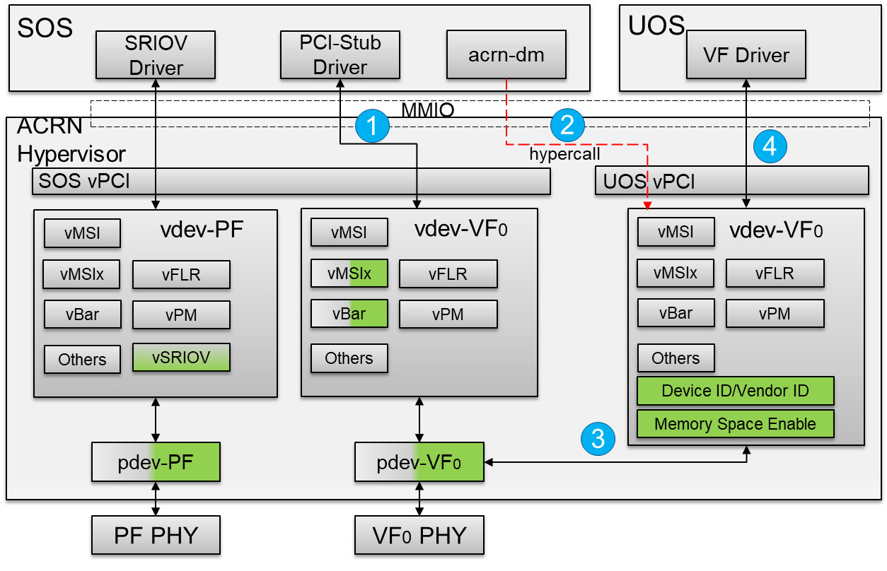
Figure 81 SR-IOV VF Passthrough Architecture In ACRN
- The SR-IOV VF device needs to bind the PCI-stud driver instead of the vendor-specific VF driver before the device passthrough.
- The user configures the
acrn-dmboot parameter with the passthrough SR-IOV VF device. When the User VM starts,acrn-dminvokes a hypercall to set the vdev-VF0 device in the User VM. - The hypervisor emulates Device ID/Vendor ID and Memory Space Enable (MSE) in the configuration space for an assigned SR-IOV VF device. The assigned VF Device ID comes from its associated PF’s capability. The Vendor ID is the same as the PF’s Vendor ID and the MSE is always set when reading the SR-IOV VF device’s CONTROL register.
- The vendor-specific VF driver in the target VM probes the assigned SR-IOV VF device.
SR-IOV Initialization Flow
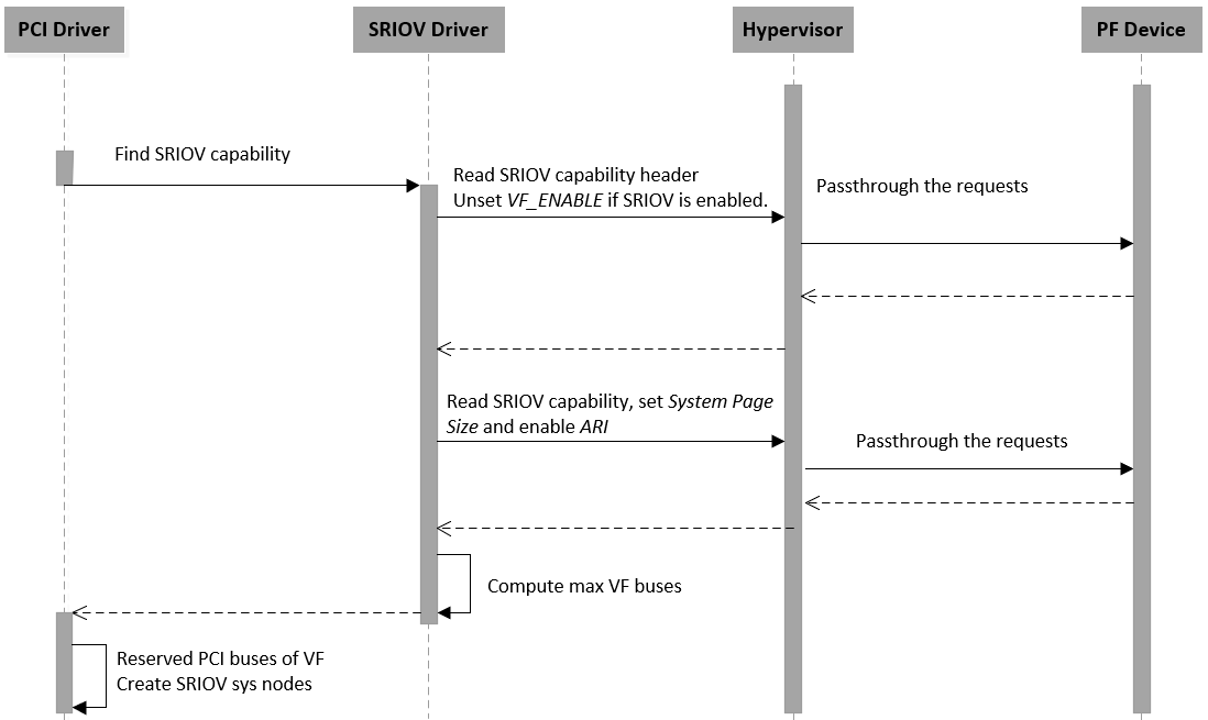
Figure 82 SR-IOV Initialization Flow
When a SR-IOV capable device is initialized, all access to the configuration space will passthrough to the physical device directly. The Service VM can identify all capabilities of the device from the SR-IOV extended capability and then create an sysfs node for SR-IOV management.
SR-IOV VF Enable Flow
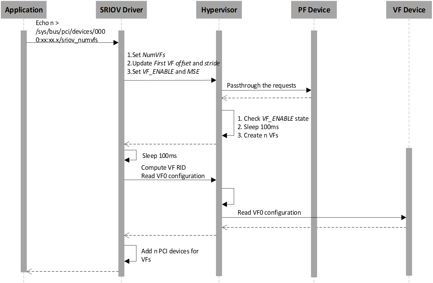
Figure 83 SR-IOV VF Enable Flow
The application enables n VF devices via a SR-IOV PF device sysfs node. The hypervisor intercepts all SR-IOV capability access and checks the VF_ENABLE state. If VF_ENABLE is set, the hypervisor creates n virtual devices after 100ms so that VF physical devices have enough time to be created. The Service VM waits 100ms and then only accesses the first VF device’s configuration space including Class Code, Reversion ID, Subsystem Vendor ID, Subsystem ID. The Service VM uses the first VF device information to initialize subsequent VF devices.
SR-IOV VF Disable Flow
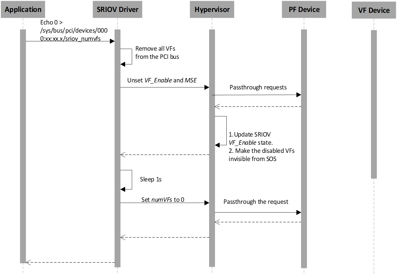
Figure 84 SR-IOV VF Disable Flow
The application disables SR-IOV VF devices by writing zero to the SR-IOV PF device sysfs node. The hypervisor intercepts all SR-IOV capability accesses and checks the VF_ENABLE state. If VF_ENABLE is clear, the hypervisor makes VF virtual devices invisible from the Service VM so that all access to VF devices will return 0xFFFFFFFF as an error. The VF physical devices are removed within 1s of when VF_ENABLE is clear.
SR-IOV VF Assignment Policy
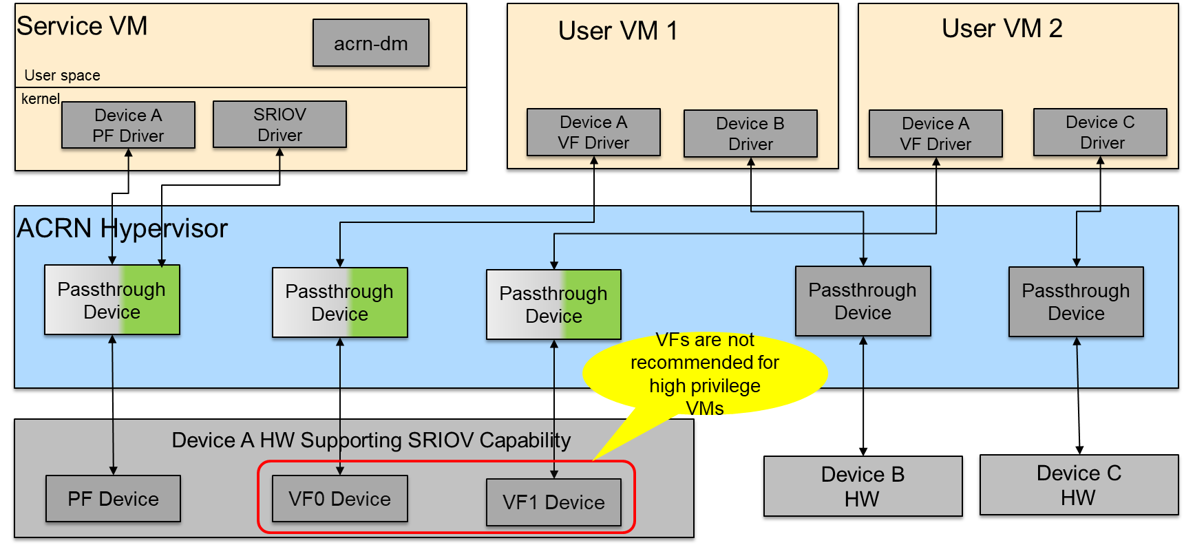
Figure 85 SR-IOV VF Assignment
- All SR-IOV PF devices are managed by the Service VM.
- Currently, the SR-IOV PF cannot passthrough to the User VM.
- All VFs can passthrough to the User VM, but we do not recommend a passthrough to high privilege VMs because the PF device may impact the assigned VFs’ functionality and stability.
SR-IOV Usage Guide In ACRN
We use the Intel 82576 NIC as an example in the following instructions. We only support LaaG (Linux as a Guest).
Ensure that the 82576 VF driver is compiled into the User VM Kernel (set CONFIG_IGBVF=y in the Kernel Config).
When the Service VM boots up, the
\ *lspci -v*\command indicates that the Intel 82576 NIC devices have SR-IOV capability and their PF drivers areigb.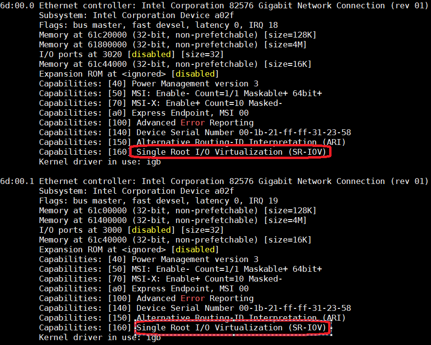
Figure 86 82576 SR-IOV PF devices
Input the
\ *echo n > /sys/class/net/enp109s0f0/device/sriov\_numvfs*\command in the Service VM to enable n VF devices for the first PF device (enp109s0f0). The number n can’t be more than TotalVFs which comes from the return value of commandcat /sys/class/net/enp109s0f0/device/sriov\_totalvfs. Here we use n = 2 as an example.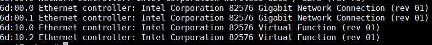
Figure 87 82576 SR-IOV VF devices
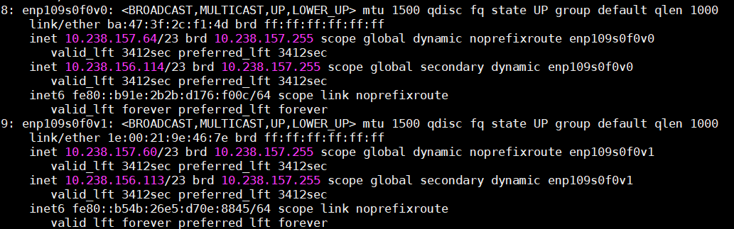
Figure 88 82576 SR-IOV VF NIC
Passthrough a SR-IOV VF device to guest.
Unbind the igbvf driver in the Service VM.
- modprobe pci_stub
- echo “8086 10ca” > /sys/bus/pci/drivers/pci-stub/new_id
- echo “0000:6d:10.0” > /sys/bus/pci/devices/0000:6d:10.0/driver/unbind
- echo “0000:6d:10.0” > /sys/bus/pci/drivers/pci-stub/bind
Add the SR-IOV VF device parameter (“-s X, passthru,6d/10/0”) in the launch User VM script
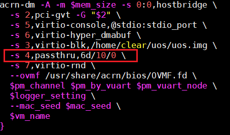
Figure 89 Configure 82576 NIC as a Passthrough Device
Boot the User VM
SR-IOV Limitations In ACRN
- The SR-IOV migration feature is not supported.
- If one SR-IOV PF device is detected during the enumeration phase, but not enough room exists for its total VF devices, the PF device will be dropped. The platform uses the MAX_PCI_DEV_NUM ACRN configuration to support the maximum number of PCI devices. Make sure MAX_PCI_DEV_NUM is more than the number of all PCI devices, including the total SR-IOV VF devices.