ACRN high-level design overview
ACRN is an open source reference hypervisor (HV) that runs on top of Intel platforms (APL, KBL, etc) for heterogeneous scenarios such as the Software Defined Cockpit (SDC), or the In-Vehicle Experience (IVE) for automotives, or HMI & Real-Time OS for industry. ACRN provides embedded hypervisor vendors with a reference I/O mediation solution with a permissive license and provides auto makers and industry users a reference software stack for corresponding use.
ACRN Supported Use Cases
Software Defined Cockpit
The SDC system consists of multiple systems: the instrument cluster (IC) system, the In-vehicle Infotainment (IVI) system, and one or more rear seat entertainment (RSE) systems. Each system runs as a VM for better isolation.
The Instrument Control (IC) system manages graphic displays of
- driving speed, engine RPM, temperature, fuel level, odometer, trip mile, etc.
- alerts of low fuel or tire pressure
- rear-view camera (RVC) and surround-camera view for driving assistance
In-Vehicle Infotainment
A typical In-Vehicle Infotainment (IVI) system supports:
- Navigation systems
- Radios, audio and video playback
- Mobile devices connection for calls, music, and applications via voice recognition and/or gesture Recognition / Touch
- Rear-seat RSE services such as:
- entertainment system
- virtual office
- connection to IVI front system and mobile devices (cloud connectivity)
ACRN supports guest OSes of Clear Linux OS and Android. OEMs can use the ACRN hypervisor and the Linux or Android guest OS reference code to implement their own VMs for a customized IC/IVI/RSE.
Industry Usage
A typical industry usage would include one windows HMI + one RT VM:
- windows HMI as a guest OS with display to provide Human Machine Interface
- RT VM which running specific RTOS on it to provide capability of handling real-time workloads like PLC control
ACRN supports guest OS of Windows; ACRN has also added/is adding a series features to enhance its real-time performance then meet hard-RT KPI for its RT VM:
- CAT (Cache Allocation Technology)
- MBA (Memory Bandwidth Allocation)
- LAPIC pass-thru
- Polling mode driver
- ART (always running timer)
- other TCC features like split lock detection, Pseudo locking for cache
Hardware Requirements
Mandatory IA CPU features are support for:
- Long mode
- MTRR
- TSC deadline timer
- NX, SMAP, SMEP
- Intel-VT including VMX, EPT, VT-d, APICv, VPID, invept and invvpid
Recommended Memory: 4GB, 8GB preferred.
ACRN Architecture
ACRN is a type-I hypervisor that runs on top of bare metal. It supports Intel APL & KBL platforms and can be easily extended to support future platforms. ACRN implements a hybrid VMM architecture, using a privileged service VM to manage I/O devices and provide I/O mediation. Multiple user VMs can be supported, running Clear Linux OS or Android OS as the User VM.
ACRN 1.0
ACRN 1.0 is designed mainly for auto use cases such as SDC & IVI.
Instrument cluster applications are critical in the Software Defined Cockpit (SDC) use case, and may require functional safety certification in the future. Running the IC system in a separate VM can isolate it from other VMs and their applications, thereby reducing the attack surface and minimizing potential interference. However, running the IC system in a separate VM introduces additional latency for the IC applications. Some country regulations requires an IVE system to show a rear-view camera (RVC) within 2 seconds, which is difficult to achieve if a separate instrument cluster VM is started after the User VM is booted.
Figure 117 shows the architecture of ACRN 1.0 together with the IC VM and Service VM. As shown, the Service VM owns most of platform devices and provides I/O mediation to VMs. Some of the PCIe devices function as a pass-through mode to User VMs according to VM configuration. In addition, the Service VM could run the IC applications and HV helper applications such as the Device Model, VM manager, etc. where the VM manager is responsible for VM start/stop/pause, virtual CPU pause/resume, etc.
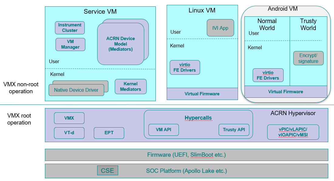
Figure 117 ACRN 1.0 Architecture
ACRN 2.0
ACRN 2.0 is extending ACRN to support pre-launched VM (mainly for safety VM) and Real-Time (RT) VM.
Figure 118 shows the architecture of ACRN 2.0; the main difference compared to ACRN 1.0 is that:
- a pre-launched VM is supported in ACRN 2.0, with isolated resources, including CPU, memory, and HW devices, etc
- ACRN 2.0 adds a few necessary device emulations in hypervisor like vPCI and vUART to avoid interference between different VMs
- ACRN 2.0 supports RT VM for a post-launched User VM, with assistant features like LAPIC pass-thru and PMD virtio driver
ACRN 2.0 is still WIP, and some of its features are already merged in the master.
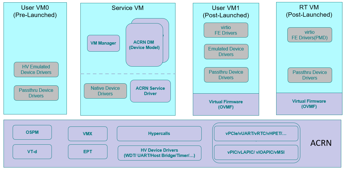
Figure 118 ACRN 2.0 Architecture
Device Emulation
ACRN adopts various approaches for emulating devices for the User VM:
- Emulated device: A virtual device using this approach is emulated in
the Service VM by trapping accesses to the device in the User VM. Two sub-categories
exist for emulated device:
- fully emulated, allowing native drivers to be used unmodified in the User VM, and
- para-virtualized, requiring front-end drivers in the User VM to function.
- Pass-through device: A device passed through to the User VM is fully accessible to the User VM without interception. However, interrupts are first handled by the hypervisor before being injected to the User VM.
- Mediated pass-through device: A mediated pass-through device is a hybrid of the previous two approaches. Performance-critical resources (mostly data-plane related) are passed-through to the User VMs and others (mostly control-plane related) are emulated.
I/O Emulation
The device model (DM) is a place for managing User VM devices: it allocates memory for the User VMs, configures and initializes the devices shared by the guest, loads the virtual BIOS and initializes the virtual CPU state, and invokes the hypervisor service to execute the guest instructions.
The following diagram illustrates the control flow of emulating a port I/O read from the User VM.
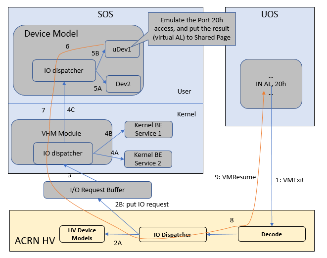
Figure 119 I/O (PIO/MMIO) Emulation Path
Figure 119 shows an example I/O emulation flow path.
When a guest executes an I/O instruction (port I/O or MMIO), an VM exit
happens. The HV takes control and executes the request based on the VM exit
reason VMX_EXIT_REASON_IO_INSTRUCTION for port I/O access, for
example. The HV will then fetch the additional guest instructions, if any,
and processes the port I/O instructions at a pre-configured port address
(in AL, 20h for example), and place the decoded information such as
the port I/O address, size of access, read/write, and target register
into the I/O request in the I/O request buffer (shown in
Figure 119) and then notify/interrupt the Service VM to process.
The virtio and HV service module (VHM) in the Service VM intercepts HV interrupts, and accesses the I/O request buffer for the port I/O instructions. It will then check to see if any kernel device claims ownership of the I/O port. The owning device, if any, executes the requested APIs from a VM. Otherwise, the VHM module leaves the I/O request in the request buffer and wakes up the DM thread for processing.
DM follows the same mechanism as VHM. The I/O processing thread of the DM queries the I/O request buffer to get the PIO instruction details and checks to see if any (guest) device emulation modules claim ownership of the I/O port. If yes, the owning module is invoked to execute requested APIs.
When the DM completes the emulation (port IO 20h access in this example) of a device such as uDev1, uDev1 will put the result into the request buffer (register AL). The DM will then return the control to HV indicating completion of an IO instruction emulation, typically thru VHM/hypercall. The HV then stores the result to the guest register context, advances the guest IP to indicate the completion of instruction execution, and resumes the guest.
MMIO access path is similar except for a VM exit reason of EPT violation.
DMA Emulation
Currently the only fully virtualized devices to the User VM are USB xHCI, UART, and Automotive I/O controller. None of these require emulating DMA transactions. ACRN does not currently support virtual DMA.
Hypervisor
ACRN takes advantage of Intel Virtualization Technology (Intel VT). The ACRN HV runs in Virtual Machine Extension (VMX) root operation, host mode, or VMM mode, while the Service and User VM guests run in VMX non-root operation, or guest mode. (We’ll use “root mode” and “non-root mode” for simplicity).
The VMM mode has 4 rings. ACRN runs HV in ring 0 privilege only, and leaves ring 1-3 unused. A guest running in non-root mode has its own full rings (ring 0 to 3). The guest kernel runs in ring 0 in guest mode, while the guest user land applications run in ring 3 of guest mode (ring 1 and 2 are usually not used by commercial OS).
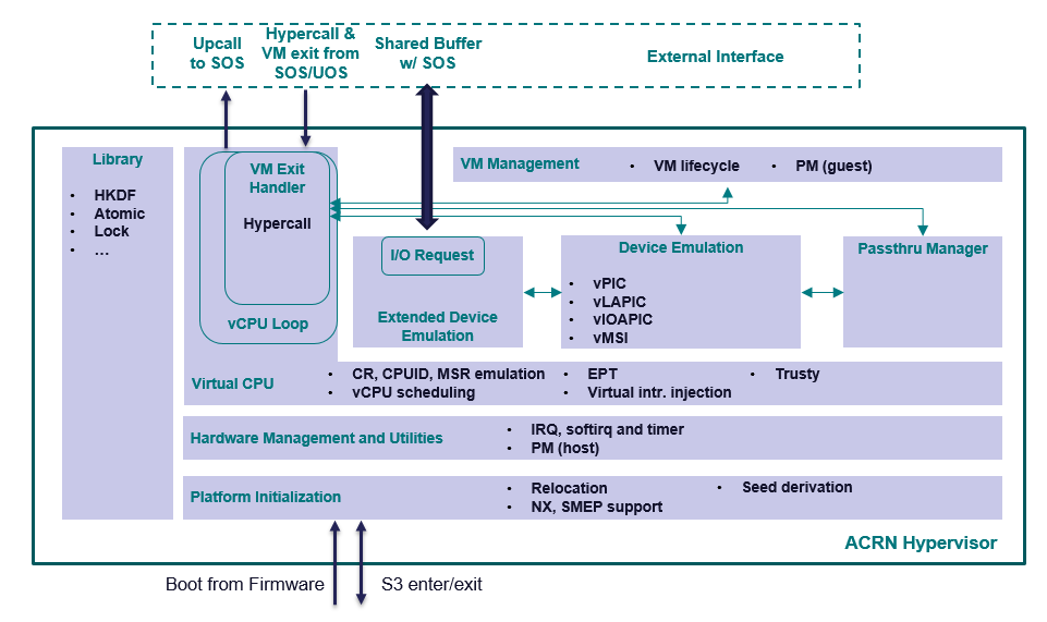
Figure 120 Architecture of ACRN hypervisor
Figure 120 shows an overview of the ACRN hypervisor architecture.
- A platform initialization layer provides an entry point, checking hardware capabilities and initializing the processors, memory, and interrupts. Relocation of the hypervisor image, derivation of encryption seeds are also supported by this component.
- A hardware management and utilities layer provides services for managing physical resources at runtime. Examples include handling physical interrupts and low power state changes.
- A layer sitting on top of hardware management enables virtual CPUs (or vCPUs), leveraging Intel VT. A vCPU loop runs a vCPU in non-root mode and handles VM exit events triggered by the vCPU. This layer handles CPU and memory-related VM exits and provides a way to inject exceptions or interrupts to a vCPU.
- On top of vCPUs are three components for device emulation: one for emulation inside the hypervisor, another for communicating with the Service VM for mediation, and the third for managing pass-through devices.
- The highest layer is a VM management module providing VM lifecycle and power operations.
- A library component provides basic utilities for the rest of the hypervisor, including encryption algorithms, mutual-exclusion primitives, etc.
There are three ways that the hypervisor interacts with the Service VM: the VM exits (including hypercalls), upcalls, and through the I/O request buffer. Interaction between the hypervisor and the User VM is more restricted, including only VM exits and hypercalls related to trusty.
Service VM
The Service VM is an important guest OS in the ACRN architecture. It runs in non-root mode, and contains many critical components, including the VM manager, the device model (DM), ACRN services, kernel mediation, and virtio and hypercall modules (VHM). The DM manages the User VM and provides device emulation for it. The User VMS also provides services for system power lifecycle management through the ACRN service and VM manager, and services for system debugging through ACRN log/trace tools.
DM
DM (Device Model) is a user-level QEMU-like application in the Service VM responsible for creating the User VM and then performing devices emulation based on command line configurations.
Based on a VHM kernel module, DM interacts with VM manager to create the User VM. It then emulates devices through full virtualization on the DM user level, or para-virtualized based on kernel mediator (such as virtio, GVT), or pass-through based on kernel VHM APIs.
Refer to Device Model high-level design for more details.
VM Manager
VM Manager is a user-level service in the Service VM handling User VM creation and VM state management, according to the application requirements or system power operations.
VM Manager creates the User VM based on DM application, and does User VM state management by interacting with lifecycle service in ACRN service.
Please refer to VM management chapter for more details.
ACRN Service
ACRN service provides system lifecycle management based on IOC polling. It communicates with the VM manager to handle the User VM state, such as S3 and power-off.
VHM
The VHM (virtio & hypercall module) kernel module is the Service VM kernel driver supporting User VM management and device emulation. Device Model follows the standard Linux char device API (ioctl) to access VHM functionalities. VHM communicates with the ACRN hypervisor through hypercall or upcall interrupts.
Refer to the VHM chapter for more details.
Kernel Mediators
Kernel mediators are kernel modules providing a para-virtualization method for the User VMs, for example, an i915 gvt driver.
Log/Trace Tools
ACRN Log/Trace tools are user-level applications used to capture ACRN hypervisor log and trace data. The VHM kernel module provides a middle layer to support these tools.
Refer to Tracing and Logging high-level design for more details.
User VM
Currently, ACRN can boot Linux and Android guest OSes. For Android guest OS, ACRN provides a VM environment with two worlds: normal world and trusty world. The Android OS runs in the normal world. The trusty OS and security sensitive applications run in the trusty world. The trusty world can see the memory of normal world, but normal world cannot see trusty world.
Guest Physical Memory Layout - User VM E820
DM will create E820 table for a User VM based on these simple rules:
- If requested VM memory size < low memory limitation (currently 2 GB, defined in DM), then low memory range = [0, requested VM memory size]
- If requested VM memory size > low memory limitation, then low memory range = [0, 2G], and high memory range = [4G, 4G + requested VM memory size - 2G]
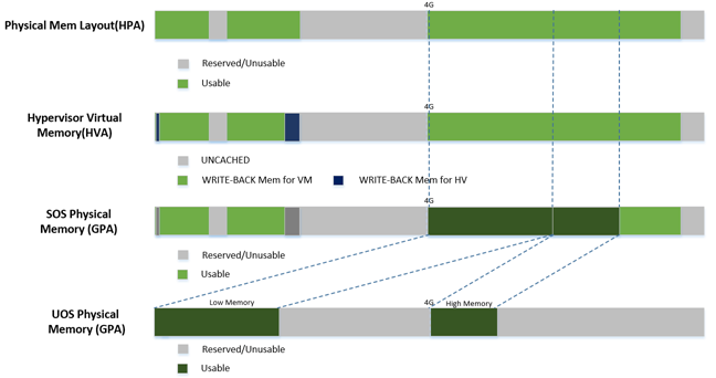
Figure 121 User VM Physical Memory Layout
User VM Memory Allocation
The DM does User VM memory allocation based on the hugetlb mechanism by default. The real memory mapping may be scattered in the Service VM physical memory space, as shown in Figure 122:
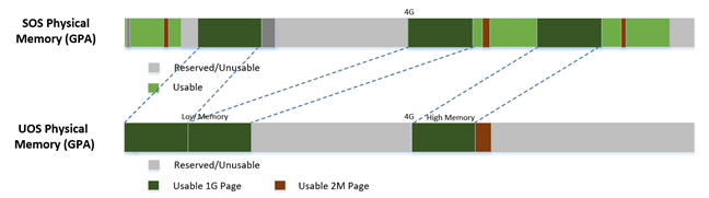
Figure 122 User VM Physical Memory Layout Based on Hugetlb
The User VM’s memory is allocated by Service OS DM application; it may come from different huge pages in Service OS as shown in Figure 122.
As the Service VM has full knowledge of these huge pages size, GPASOS and GPAUOS, it works with the hypervisor to complete the User VM’s host-to-guest mapping using this pseudo code:
Virtual Slim bootloader
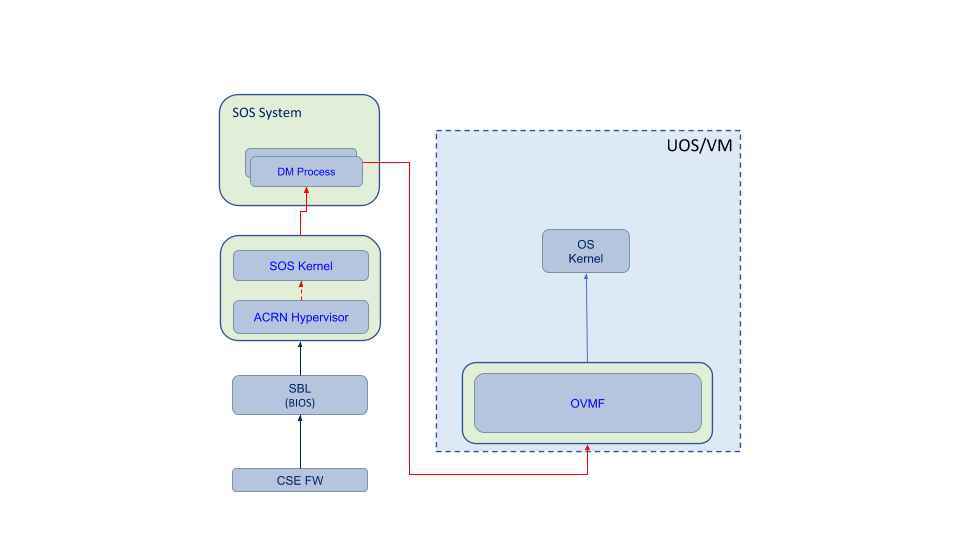
The Virtual Slim bootloader (vSBL) is the virtual bootloader that supports booting the User VM on the ACRN hypervisor platform. The vSBL design is derived from Slim Bootloader. It follows a staged design approach that provides hardware initialization and payload launching that provides the boot logic. As shown in Figure 123, the virtual SBL has an initialization unit to initialize virtual hardware, and a payload unit to boot Linux or Android guest OS.
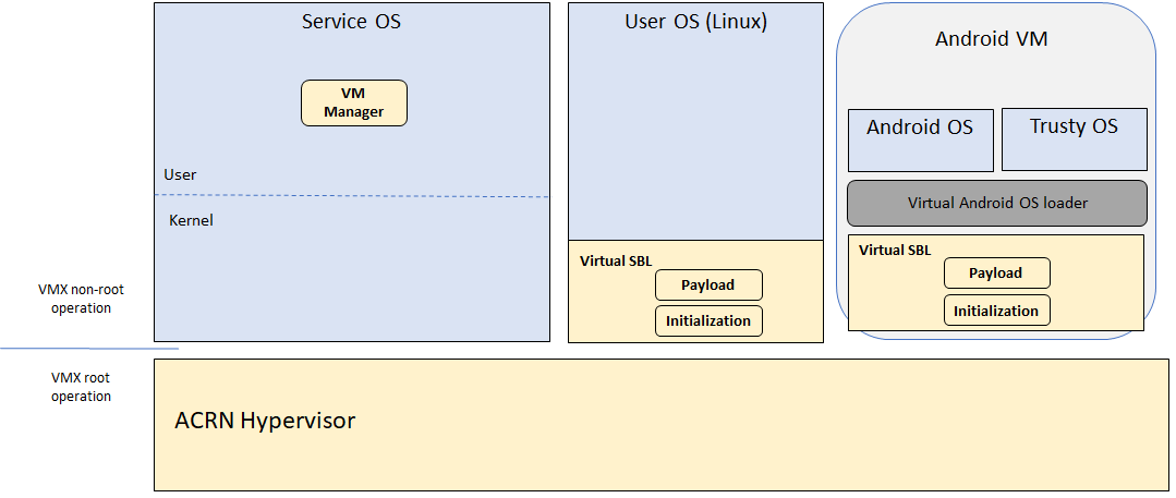
Figure 123 vSBL System Context Diagram
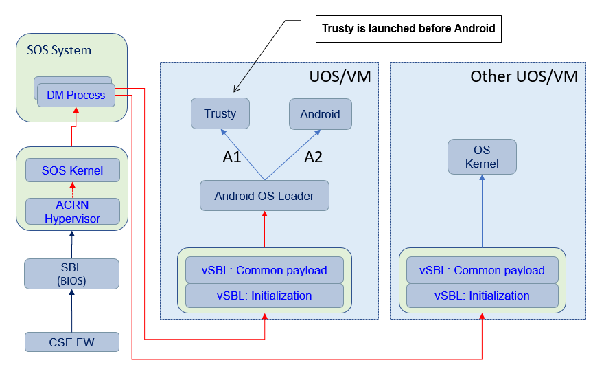
The vSBL image is released as a part of the Service OS root filesystem (rootfs). The vSBL is copied to the User VM memory by the VM manager in the Service VM while creating the User VM virtual BSP of the User VM. The Service VM passes the start of vSBL and related information to HV. HV sets the guest RIP of the User VM’s virtual BSP as the start of vSBL and related guest registers, and launches the User VM virtual BSP. The vSBL starts running in the virtual real mode within the User VM. Conceptually, vSBL is part of the User VM runtime.
In the current design, the vSBL supports booting Android guest OS or Linux guest OS using the same vSBL image.
For an Android VM, the vSBL will load and verify trusty OS first, and trusty OS will then load and verify Android OS according to the Android OS verification mechanism.
OVMF bootloader
Open Virtual Machine Firmware (OVMF) is the virtual bootloader that supports the EFI boot of the User VM on the ACRN hypervisor platform.
The OVMF is copied to the User VM memory by the VM manager in the Service VM while creating the User VM virtual BSP of the User VM. The Service VM passes the start of OVMF and related information to HV. HV sets guest RIP of the User VM virtual BSP as the start of OVMF and related guest registers, and launches the User VM virtual BSP. The OVMF starts running in the virtual real mode within the User VM. Conceptually, OVMF is part of the User VM runtime.
Freedom From Interference
The hypervisor is critical for preventing inter-VM interference, using the following mechanisms:
Each physical CPU is dedicated to one vCPU.
CPU sharing is in the TODO list, but talking about inter-VM interference, sharing a physical CPU among multiple vCPUs gives rise to multiple sources of interference such as the vCPU of one VM flushing the L1 & L2 cache for another, or tremendous interrupts for one VM delaying the execution of another. It also requires vCPU scheduling in the hypervisor to consider more complexities such as scheduling latency and vCPU priority, exposing more opportunities for one VM to interfere another.
To prevent such interference, ACRN hypervisor could adopts static core partitioning by dedicating each physical CPU to one vCPU. The physical CPU loops in idle when the vCPU is paused by I/O emulation. This makes the vCPU scheduling deterministic and physical resource sharing is minimized.
Hardware mechanisms including EPT, VT-d, SMAP and SMEP are leveraged to prevent unintended memory accesses.
Memory corruption can be a common failure mode. ACRN hypervisor properly sets up the memory-related hardware mechanisms to ensure that:
- The Service VM cannot access the memory of the hypervisor, unless explicitly allowed
- The User VM cannot access the memory of the Service VM and the hypervisor
- The hypervisor does not unintendedly access the memory of the Service or User VM.
Destination of external interrupts are set to be the physical core where the VM that handles them is running.
External interrupts are always handled by the hypervisor in ACRN. Excessive interrupts to one VM (say VM A) could slow down another VM (VM B) if they are handled by the physical core running VM B instead of VM A. Two mechanisms are designed to mitigate such interference.
- The destination of an external interrupt is set to the physical core that runs the vCPU where virtual interrupts will be injected.
- The hypervisor maintains statistics on the total number of received interrupts to the Service VM via a hypercall, and has a delay mechanism to temporarily block certain virtual interrupts from being injected. This allows the Service VM to detect the occurrence of an interrupt storm and control the interrupt injection rate when necessary.
Mitigation of DMA storm.
(To be documented later.)
Power Management
CPU P-state & C-state
In ACRN, CPU P-state and C-state (Px/Cx) are controlled by the guest OS. The corresponding governors are managed in the Service/User VM for best power efficiency and simplicity.
Guests should be able to process the ACPI P/C-state request from OSPM. The needed ACPI objects for P/C-state management should be ready in ACPI table.
Hypervisor can restrict guest’s P/C-state request (per customer requirement). MSR accesses of P-state requests could be intercepted by the hypervisor and forwarded to the host directly if the requested P-state is valid. Guest MWAIT/Port IO accesses of C-state control could be passed through to host with no hypervisor interception to minimize performance impacts.
This diagram shows CPU P/C-state management blocks:
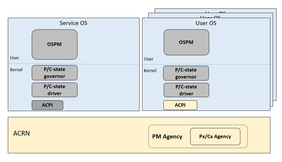
Figure 125 CPU P/C-state management block diagram
System power state
ACRN supports ACPI standard defined power state: S3 and S5 in system level. For each guest, ACRN assume guest implements OSPM and controls its own power state accordingly. ACRN doesn’t involve guest OSPM. Instead, it traps the power state transition request from guest and emulates it.
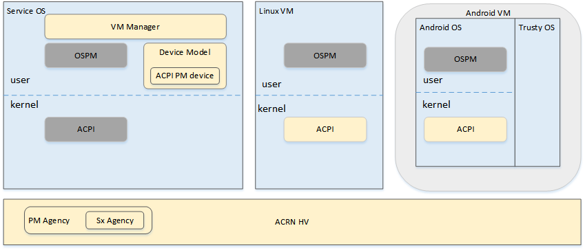
Figure 126 ACRN Power Management Diagram Block
Figure 126 shows the basic diagram block for ACRN PM. The OSPM in each guest manages the guest power state transition. The Device Model running in the Service VM traps and emulates the power state transition of the User VM (Linux VM or Android VM in Figure 126). VM Manager knows all User VM power states and notifies the OSPM of the Service VM (Service OS in Figure 126) once active the User VM is in the required power state.
Then the OSPM of the Service VM starts the power state transition of the Service VM which is trapped to “Sx Agency” in ACRN, and it will start the power state transition.
Some details about the ACPI table for the User and Service VMs:
- The ACPI table in the User VM is emulated by the Device Model. The Device Model knows which register the User VM writes to trigger power state transitions. Device Model must register an I/O handler for it.
- The ACPI table in the Service VM is passthru. There is no ACPI parser in ACRN HV. The power management related ACPI table is generated offline and hardcoded in ACRN HV.