USB Virtualization
Universal Serial Bus (USB) is an industry standard that establishes specifications for cables, connectors, and protocols for connection, communication, and power supply between personal computers and their peripheral devices.
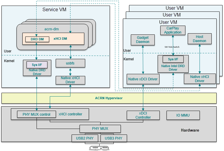
Figure 183 USB Architecture Overview
The ACRN USB virtualization includes emulation of three components, described here and shown in Figure 183:
xHCI DM (Host Controller Interface) provides multiple instances of virtual xHCI controllers to share among multiple User VMs, each USB port can be assigned and dedicated to a VM by user settings.
xDCI controller (Device Controller Interface) can be passed through to the specific User VM with I/O MMU assistance.
DRD DM (Dual Role Device) emulates the PHY MUX control logic. The sysfs interface in a User VM is used to trap the switch operation into DM, and the sysfs interface in the Service VM is used to operate on the physical registers to switch between DCI and HCI role.
On Apollo Lake platforms, the sysfs interface path is
/sys/class/usb_role/intel_xhci_usb_sw/role. If the user echos the stringdeviceto the role node, the USB PHY will be connected with the xDCI controller as device mode. Similarly, by echoinghost, the USB PHY will be connected with the xHCI controller as host mode.
An xHCI register access from a User VM will induce an EPT trap from the User VM to DM, and the xHCI DM or DRD DM will emulate hardware behaviors to make the subsystem run.
USB Host Virtualization
USB host virtualization is implemented as shown in Figure 184:
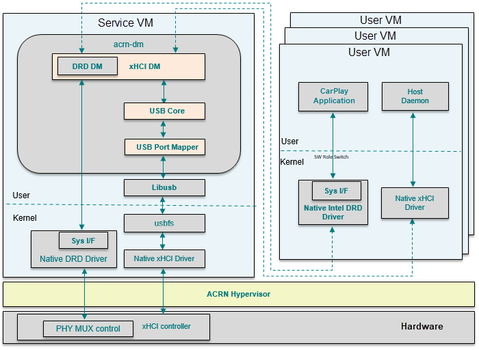
Figure 184 xHCI DM Software Architecture
The following components make up the ACRN USB stack supporting xHCI DM:
xHCI DM emulates the xHCI controller logic following the xHCI spec.
USB core is a middle abstract layer to isolate the USB controller emulators and USB device emulators.
USB Port Mapper maps the specific native physical USB ports to virtual USB ports. It communicates with native USB ports though libusb.
All the USB data buffers from a User VM are in the form of TRB
(Transfer Request Blocks), according to xHCI spec. xHCI DM will fetch
these data buffers when the related xHCI doorbell registers are set.
The data will convert to struct usb_data_xfer and, through USB core,
forward to the USB port mapper module which will communicate with the native USB
stack over libusb.
The Device Model configuration command syntax for xHCI is as follows:
-s <slot>,xhci,[bus1-port1,bus2-port2]
slot: virtual PCI slot number in DM
bus-port: specify which physical USB ports need to map to a User VM.
A simple example:
-s 7,xhci,1-2,2-2
This configuration means the virtual xHCI will appear in PCI slot 7 in the User VM, and any physical USB device attached on 1-2 or 2-2 will be detected by a User VM and used as expected.
USB DRD Virtualization
USB DRD (Dual Role Device) emulation works as shown in this figure:
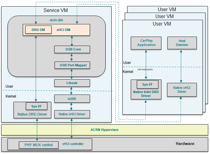
Figure 185 xHCI DRD DM Software Architecture
ACRN emulates the DRD hardware logic of an Apollo Lake platform to support the dual role requirement. The DRD feature is implemented as an xHCI vendor extended capability. ACRN emulates the same way, so the native driver can be reused in a User VM. When a User VM DRD driver reads or writes the related xHCI extended registers, these accesses will be captured by xHCI DM. xHCI DM uses the native DRD related sysfs interface to do the Host/Device mode switch operations.
The Device Model configuration command syntax for xHCI DRD is as follows:
-s <slot>,xhci,[bus1-port1,bus2-port2],cap=platform
cap: cap means virtual xHCI capability. This parameter indicates virtual xHCI should emulate the named platform’s xHCI capabilities.
A simple example:
-s 7,xhci,1-2,2-2,cap=apl
This configuration means the virtual xHCI should emulate xHCI capabilities for the Apollo Lake platform, which supports the DRD feature.
Interface Specification
Note
Reference the Doxygen-generated API content.