ACRN Shared Memory Based Inter-VM Communication
ACRN supports inter-virtual machine communication based on a shared
memory mechanism. The ACRN device model or hypervisor emulates a virtual
PCI device (called an ivshmem device) to expose the base address and
size of this shared memory.
Inter-VM Communication Overview
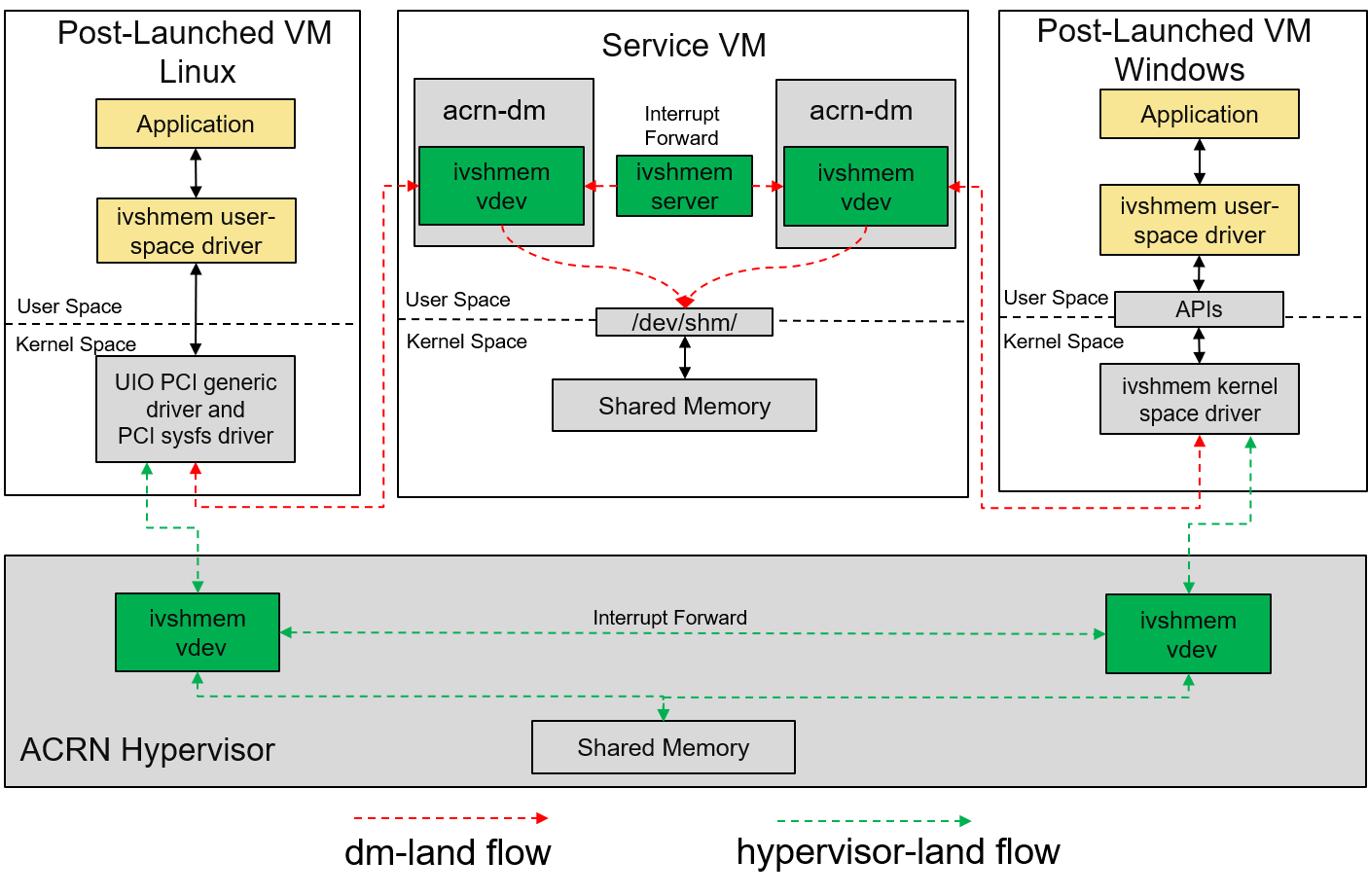
Figure 196 ACRN shared memory based inter-VM communication architecture
There are two ways ACRN can emulate the ivshmem device:
ivshmemdm-landThe
ivshmemdevice is emulated in the ACRN device model, and the shared memory regions are reserved in the Service VM’s memory space. This solution only supports communication between post-launched VMs.ivshmemhv-landThe
ivshmemdevice is emulated in the hypervisor, and the shared memory regions are reserved in the hypervisor’s memory space. This solution works for both pre-launched and post-launched VMs.
While both solutions can be used at the same time, Inter-VM communication may only be done between VMs using the same solution.
- ivshmem hv:
The ivshmem hv implements register virtualization and shared memory mapping in the ACRN hypervisor. Notification/interrupt mechanism is supported.
- ivshmem dm:
The ivshmem dm implements register virtualization and shared memory mapping in the ACRN Device Model (
acrn-dm). It will support notification/interrupt mechanism in the future.- ivshmem server:
With ivshmem server support, VMs with ivshmem devices enabled can send notification (interrupt) to each other by writing the target peer ID (VM ID) and vector index to the doorbell register of ivshmem device, ivshmem server forwards this notification event to target VM.
Two types of ivshmem server are defined in ACRN:
User land ivshmem server is a daemon in user space to forward notifications for dm-land ivshmem devices only, by co-working with ivshmem dm. User land ivshmem server is not implemented.
HV-land ivshmem server plays similar role with user land ivshmem server, but it is a hypervisor module and forwards notification (virtual interrupt) to target VM with hv-land ivshmem devices enabled.
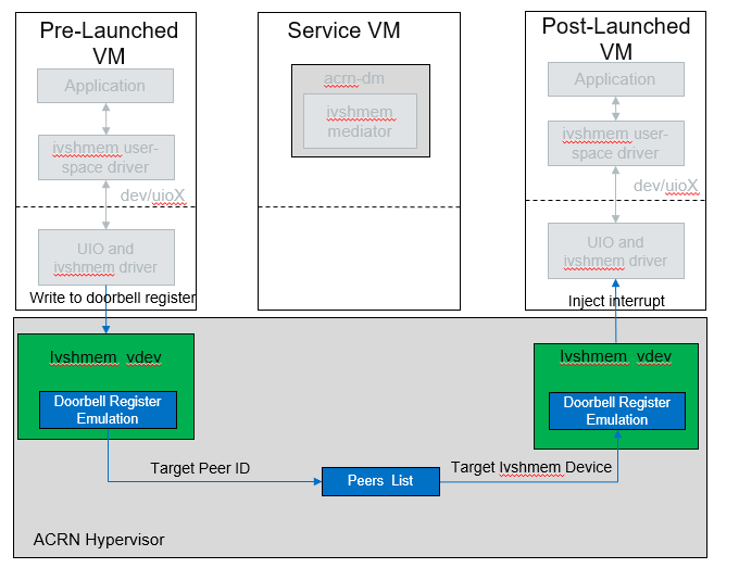
Figure 197 ACRN Ivshmem HV-Land Doorbell Overview
Ivshmem Device Introduction
The
ivshmemdevice is a virtual standard PCI device consisting of three Base Address Registers (BARs):
BAR0 is used for emulating interrupt related registers,
BAR1 is used for emulating MSIX entry table, and
BAR2 is used for exposing a shared memory region.
The
ivshmemdevice supports no extra capabilities.
Configuration Space Definition
Register |
Offset |
Value |
|---|---|---|
Vendor ID |
0x00 |
0x1AF4 |
Device ID |
0x02 |
0x1110 |
Revision ID |
0x08 |
0x1 |
Class Code |
0x09 |
0x5 |
MMIO Registers Definition
Register |
Offset |
Read/Write |
Description |
|---|---|---|---|
IVSHMEM_IRQ_MASK_REG |
0x0 |
R/W |
Interrupt Status register is used for legacy interrupt. ivshmem doesn’t support interrupts, so this is reserved. |
IVSHMEM_IRQ_STA_REG |
0x4 |
R/W |
Interrupt Mask register is used for legacy interrupt. ivshmem doesn’t support interrupts, so this is reserved. |
IVSHMEM_IV_POS_REG |
0x8 |
RO |
Inter-VM Position register is used to identify the VM ID. Currently its value is zero. |
IVSHMEM_DOORBELL_REG |
0xC |
WO |
Doorbell register is used to trigger an interrupt to the peer VM. ivshmem doesn’t support interrupts. |
Usage
For usage information, see Enable Inter-VM Communication Based on Ivshmem
Inter-VM Communication Security Hardening (BKMs)
As previously highlighted, ACRN 2.0 provides the capability to create shared memory regions between Post-Launched User VMs known as “Inter-VM Communication”. This mechanism is based on ivshmem v1.0 exposing virtual PCI devices for the shared regions (in Service VM’s memory for this release). This feature adopts a community-approved design for shared memory between VMs, following same specification for KVM/QEMU (Link).
Following the ACRN threat model, the policy definition for allocation and assignment of these regions is controlled by the Service VM, which is part of ACRN’s Trusted Computing Base (TCB). However, to secure inter-VM communication between any userspace applications that harness this channel, applications will face more requirements for the confidentiality, integrity, and authenticity of shared or transferred data. It is the application development team’s responsibility to define a threat model and security architecture for the application and utilize custom or public libraries accordingly. In this document we provide an overview about potential hardening techniques from a userspace application’s perspective. Consider these techniques when defining the security architecture and threat model for your application.
Note
This is not a definitive guide on all security technologies or how to implement security. We provide general pointers not bounded to a specific OS or use-case.
Secure Feature Configurability
ACRN ensure a minimal control plane for the configuration of the memory region’s boundaries and name handles. This is managed only by the Service VM during the creation of the guest VM through the Device Model (DM).
Service VM Admin should refer to the usage guide for secure configuration flow.
Create different permissions or groups for the
adminrole to isolate it from other entities that might have access to the Service VM. For example only admin permissions allow R/W/X on DM binary.
Apply Access Control
Add restrictions based on behavior or subject and object rules around information flow and accesses.
In Service VM, consider the
/dev/shmdevice node as a critical interface with special access requirement. Those requirements can be fulfilled using any of the existing opensource MAC technologies or even ACLs depending on the OS compatibility (Ubuntu, Windows, etc..) and integration complexity.In the User VM, the shared memory region can be accessed using
mmap()of UIO device node. Other complementary info can be found under:/sys/class/uio/uioX/device/resource2–> shared memory base address/sys/class/uio/uioX/device/config–> shared memory Size.
For Linux-based User VMs, we recommend using the standard
UIOandUIO_PCI_GENERICdrivers through the device node (for example,/dev/uioX).Reference: AppArmor, SELinux, UIO driver-API
Crypto Support and Secure Applied Crypto
According to the application’s threat model and the defined assets that need to be shared securely, define the requirements for crypto algorithms.Those algorithms should enable operations such as authenticated encryption and decryption, secure key exchange, true random number generation, and seed extraction. In addition, consider the landscape of your attack surface and define the need for security engine (for example CSME services.
Don’t implement your own crypto functions. Use available compliant crypto libraries as applicable, such as. (Intel IPP or TinyCrypt)
Utilize the platform/kernel infrastructure and services (e.g., Security High-Level Design , Kernel Crypto backend/APIs , keyring subsystem, etc..).
Implement necessary flows for key lifecycle management including wrapping,revocation and migration, depending on the crypto key type used and if there are requirements for key persistence across system and power management events.
Follow open source secure crypto coding guidelines for secure wrappers and marshalling data structures: Secure Applied Crypto
References: NIST Crypto Standards and Guidelines, OpenSSL
Applications Passlisting
For use cases implemented in static environments (for example, Industrial and Automotive usages), follow application approval techniques and disable any third-party or native app stores.
This mechanism can be chained with the access control policies to protect access to passlisting rules and configuration files (refer to opensource or implement your custom solution).
References: NIST SP800-167, fapolicyd
Secure boot and File System Integrity Verification
The previously highlighted technologies rely on the kernel, as a secure component, to enforce such policies. Because of this, we strongly recommend enabling secure boot for the Service VM, and extend the secureboot chain to any post-launched VM kernels.
To ensure no malicious software is introduced or persists, utilize the filesystem (FS) verification methods on every boot to extend the secure boot chain for post-launch VMs (kernel/FS).
Reference: Enable Secure Boot in Windows
Reference Stack: dm-verity
Note
All the mentioned hardening techniques might require minor extra development efforts.