IOC Virtualization High-Level Design
The I/O Controller (IOC) is an SoC bridge we can use to communicate with a Vehicle Bus in automotive applications, routing Vehicle Bus signals, such as those extracted from CAN messages, from the IOC to the SoC and back, as well as signals the SoC uses to control onboard peripherals.
Note
Intel NUC and UP2 platforms do not support IOC hardware, and as such, IOC virtualization is not supported on these platforms.
The main purpose of IOC virtualization is to transfer data between native Carrier Board Communication (CBC) char devices and a virtual UART. IOC virtualization is implemented as full virtualization so the User VM can directly reuse the native CBC driver.
The IOC Mediator has several virtualization requirements, such as S3/S5 wakeup reason emulation, CBC link frame packing/unpacking, signal passlist, and RTC configuration.
IOC Mediator Design
Architecture Diagrams
IOC Introduction
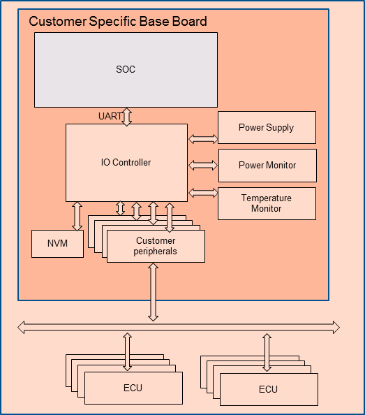
Figure 115 IOC Mediator Architecture
Vehicle Bus communication involves a wide range of individual signals to be used, varying from single GPIO signals on the IOC up to complete automotive networks that connect many external ECUs.
IOC (I/O controller) is an SoC bridge to communicate with a Vehicle Bus. It routes Vehicle Bus signals (extracted from CAN messages for example) back and forth between the IOC and SoC. It also controls the onboard peripherals from the SoC.
IOC is always turned on. The power supply of the SoC and its memory are controlled by the IOC. IOC monitors some wakeup reason to control SoC lifecycle-related features.
Some hardware signals are connected to the IOC, allowing the SoC to control them.
Besides, there is one NVM (Non-Volatile Memory) that is connected to IOC for storing persistent data. The IOC is in charge of accessing NVM following the SoC’s requirements.
CBC Protocol Introduction
The Carrier Board Communication (CBC) protocol multiplexes and prioritizes communication from the available interface between the SoC and the IOC.
The CBC protocol offers a layered approach, which allows it to run on different serial connections, such as SPI or UART.
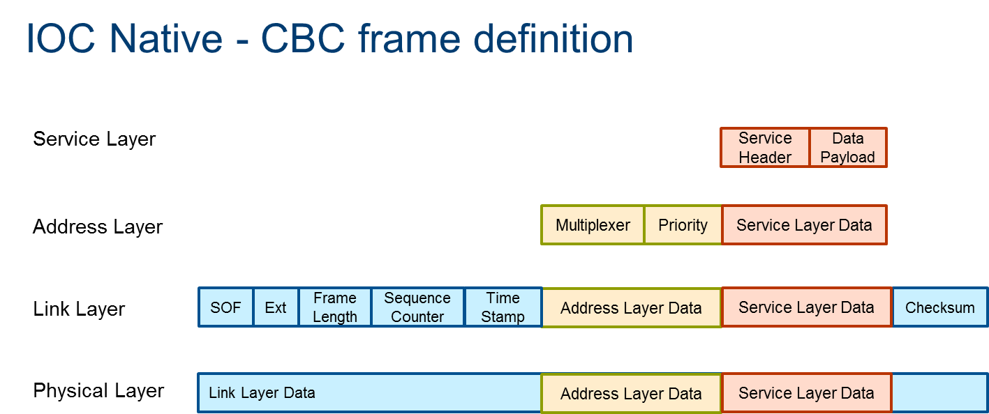
Figure 116 IOC Native - CBC Frame Definition
The CBC protocol is based on a four-layer system:
The Physical Layer is a serial interface with full duplex capabilities. A hardware handshake is required. The required bit rate depends on the peripherals connected, e.g., UART and SPI.
The Link Layer handles the length and payload verification.
The Address Layer is used to distinguish between the general data transferred. It is placed in front of the underlying Service Layer and contains Multiplexer (MUX) and Priority fields.
The Service Layer contains the payload data.
Native Architecture
In the native architecture, the IOC controller connects to UART
hardware, and communicates with the CAN bus to access peripheral
devices. cbc_attach is an application to enable the CBC ldisc
function, which creates several CBC char devices. All userspace
subsystems or services communicate with IOC firmware via the CBC char
devices.
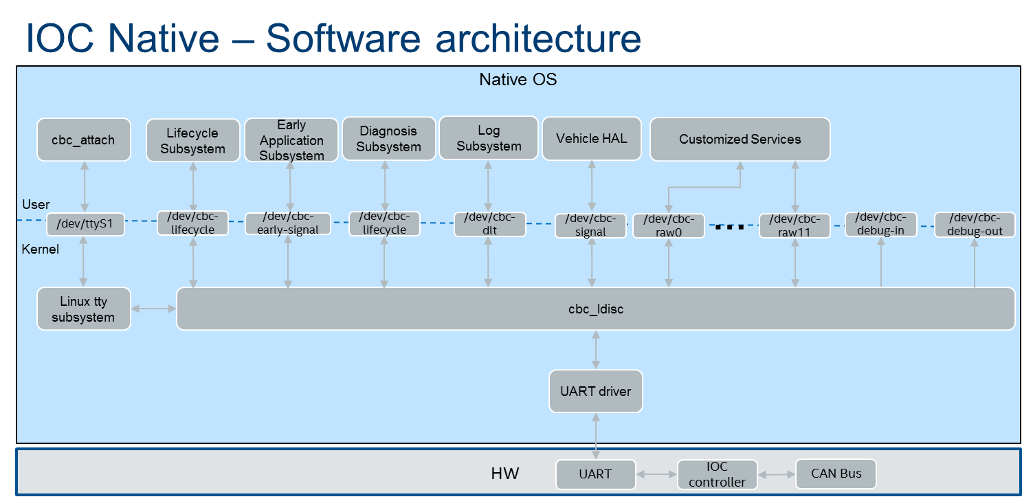
Figure 117 IOC Native - Software Architecture
Virtualization Architecture
In the virtualization architecture, the IOC Device Model (DM) is
responsible for communication between the User VM and IOC firmware. The IOC
DM communicates with several native CBC char devices and a PTY device.
The native CBC char devices only include /dev/cbc-lifecycle,
/dev/cbc-signals, and /dev/cbc-raw0 - /dev/cbc-raw11. Others
are not used by the IOC DM. IOC DM opens the /dev/ptmx device to
create a pair of devices (primary and secondary), The IOC DM uses these
devices to communicate with UART DM since UART DM needs a TTY capable
device as its backend.
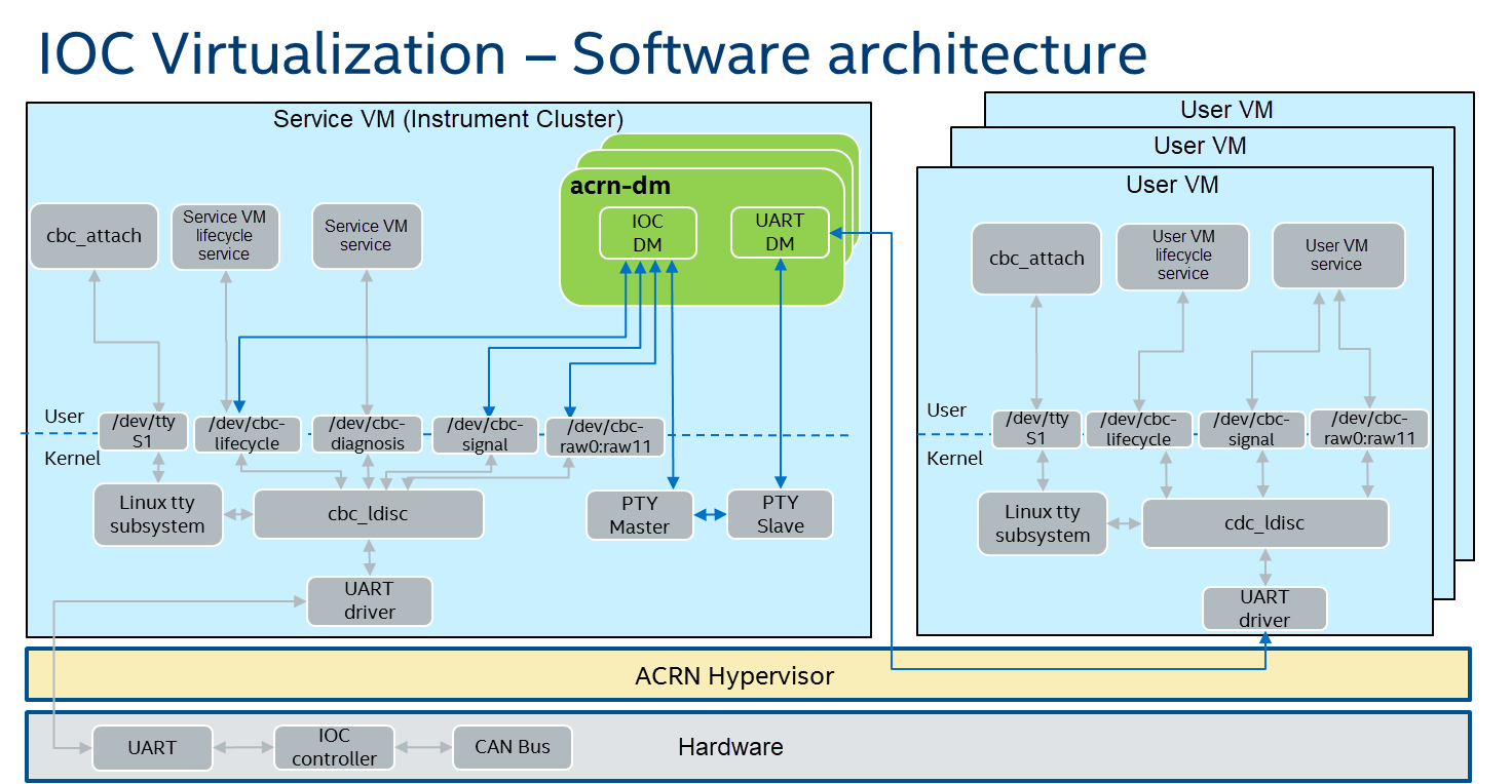
Figure 118 IOC Virtualization - Software Architecture
High-Level Design
There are five parts in this high-level design:
Software data flow introduces data transfer in the IOC mediator
State transfer introduces IOC mediator work states
CBC protocol illustrates the CBC data packing/unpacking
Power management involves boot/resume/suspend/shutdown flows
Emulated CBC commands introduce some commands workflow
IOC mediator has three threads to transfer data between User VM and Service VM. The core thread is responsible for data reception, and Tx and Rx threads are used for data transmission. Each of the transmission threads has one data queue as a buffer, so that the IOC mediator can read data from CBC char devices and UART DM immediately.
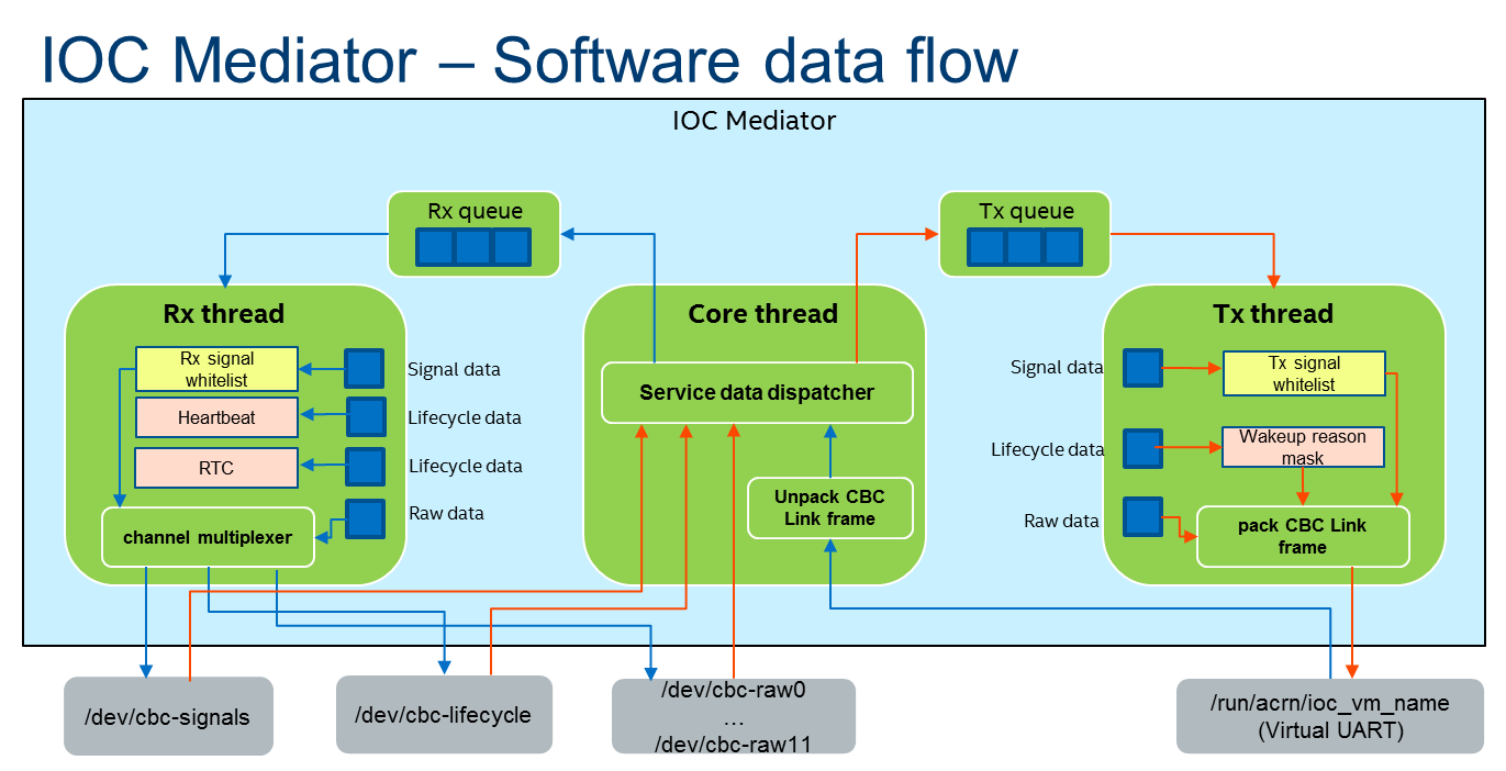
Figure 119 IOC Mediator - Software Data Flow
For Tx direction, the data comes from IOC firmware. IOC mediator receives service data from native CBC char devices such as
/dev/cbc-lifecycle. If service data is CBC wakeup reason, some wakeup reason bits will be masked. If service data is CBC signal, the data will be dropped and will not be defined in the passlist. If service data comes from a raw channel, the data will be passed forward. Before transmitting to the virtual UART interface, all data needs to be packed with an address header and link header.For Rx direction, the data comes from the User VM. The IOC mediator receives link data from the virtual UART interface. The data will be unpacked by Core thread, and then forwarded to Rx queue, similar to how the Tx direction flow is done except that the heartbeat and RTC are only used by the IOC mediator and will not be transferred to IOC firmware.
Currently, IOC mediator only cares about lifecycle, signal, and raw data. Others, e.g., diagnosis, are not used by the IOC mediator.
State Transfer
IOC mediator has four states and five events for state transfer.
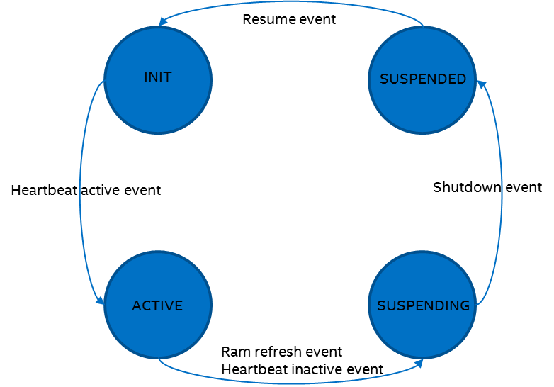
Figure 120 IOC Mediator - State Transfer
INIT state: This state is the initialized state of the IOC mediator. All CBC protocol packets are handled normally. In this state, the User VM has not yet sent an active heartbeat.
ACTIVE state: Enter this state if an HB ACTIVE event is triggered, indicating that the User VM state has been active and need to set the bit 23 (SoC bit) in the wakeup reason.
SUSPENDING state: Enter this state if a RAM REFRESH event or HB INACTIVE event is triggered. The related event handler needs to mask all wakeup reason bits except SoC bit and drop the queued CBC protocol frames.
SUSPENDED state: Enter this state if a SHUTDOWN event is triggered to close all native CBC char devices. The IOC mediator will be put to sleep until a RESUME event is triggered to re-open the closed native CBC char devices and transition to the INIT state.
CBC Protocol
IOC mediator needs to pack/unpack the CBC link frame for IOC virtualization, as shown in the detailed flow below:
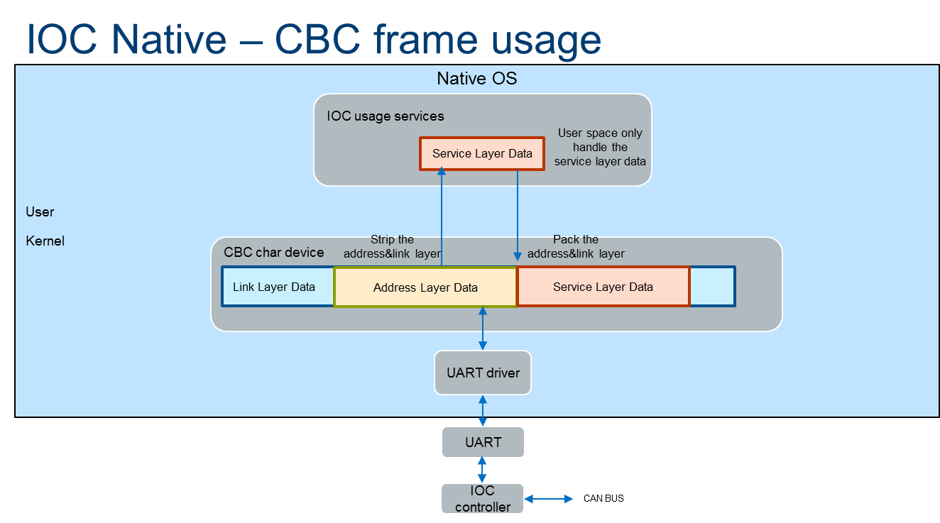
Figure 121 IOC Native - CBC Frame Usage
In the native architecture, the CBC link frame is unpacked by CBC driver. The usage services only get the service data from the CBC char devices. For data packing, CBC driver will compute the checksum and set priority for the frame, then send data to the UART driver.
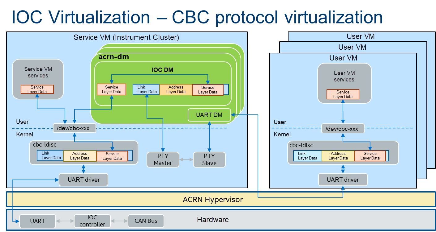
Figure 122 IOC Virtualizaton - CBC Protocol Virtualization
The difference between the native and virtualization architectures is that the IOC mediator needs to re-compute the checksum and reset priority. Currently, priority is not supported by IOC firmware; the priority setting by the IOC mediator is based on the priority setting of the CBC driver. The Service VM and User VM use the same CBC driver.
Power Management Virtualization
In acrn-dm, the IOC power management architecture involves PM DM, IOC DM, and UART DM modules. PM DM is responsible for User VM power management, and IOC DM is responsible for heartbeat and wakeup reason flows for IOC firmware. The heartbeat flow is used to control IOC firmware power state and wakeup reason flow is used to indicate IOC power state to the OS. UART DM transfers all IOC data between the Service VM and User VM. These modules complete boot/suspend/resume/shutdown functions.
Boot Flow
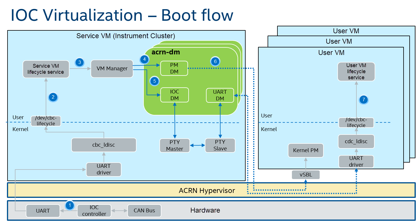
Figure 123 IOC Virtualizaton - Boot Flow
Press ignition button for booting.
Service VM lifecycle service gets a “booting” wakeup reason.
Service VM lifecycle service notifies wakeup reason to VM Manager, and VM Manager starts VM.
VM Manager sets the VM state to “start”.
IOC DM forwards the wakeup reason to User VM.
PM DM starts User VM.
User VM lifecycle gets a “booting” wakeup reason.
Suspend & Shutdown Flow
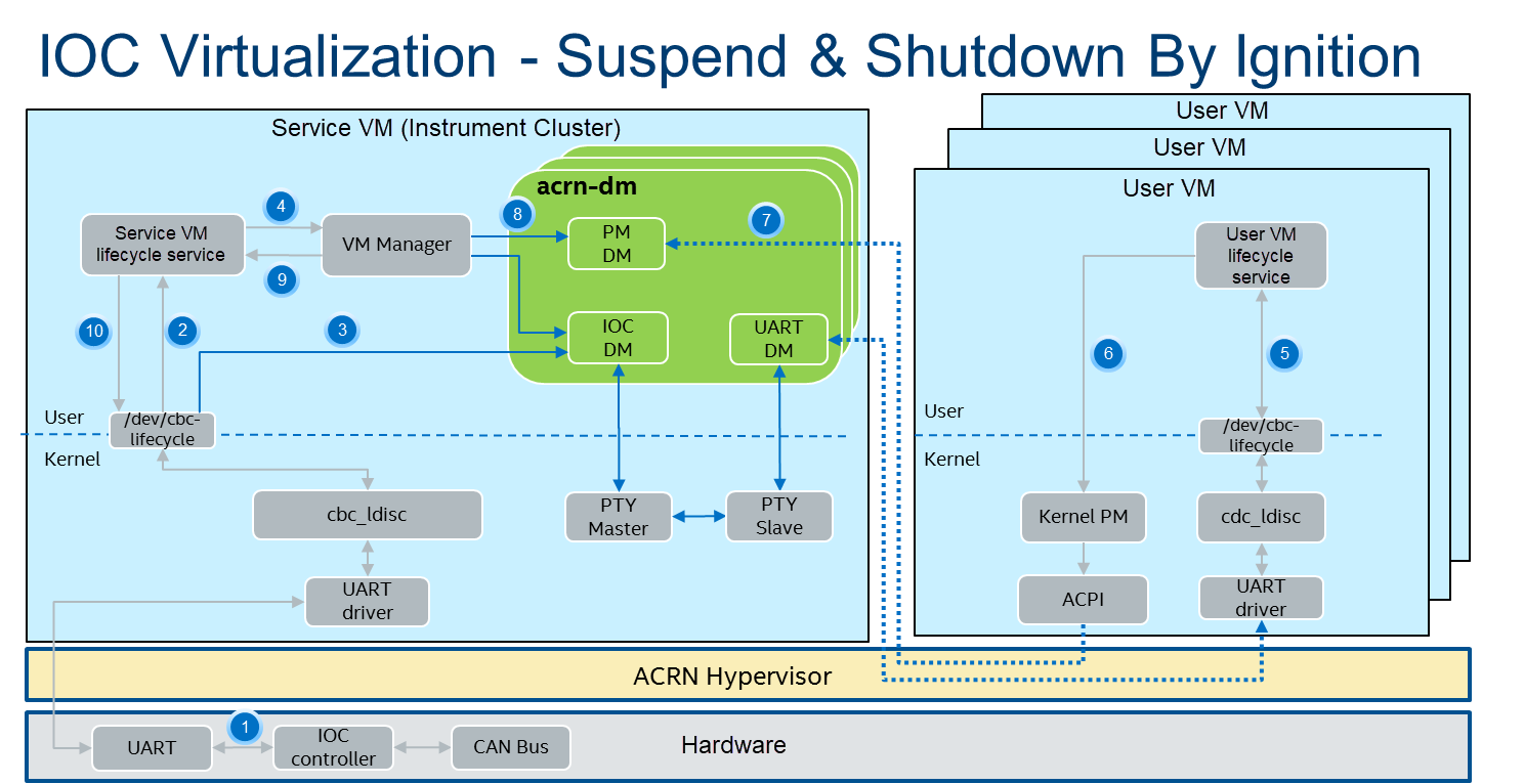
Figure 124 IOC Virtualizaton - Suspend and Shutdown by Ignition
Press ignition button to suspend or shutdown.
Service VM lifecycle service gets a 0x800000 wakeup reason, then keeps sending a shutdown delay heartbeat to IOC firmware, and notifies a “stop” event to VM Manager.
IOC DM forwards the wakeup reason to User VM lifecycle service.
Service VM lifecycle service sends a “stop” event to VM Manager, and waits for the stop response before timeout.
User VM lifecycle service gets a 0x800000 wakeup reason and sends inactive heartbeat with suspend or shutdown SUS_STAT to IOC DM.
User VM lifecycle service gets a 0x000000 wakeup reason, then enters suspend or shutdown kernel PM flow based on SUS_STAT.
PM DM executes User VM suspend/shutdown request based on ACPI.
VM Manager queries each VM state from PM DM. Suspend request maps to a paused state and shutdown request maps to a stop state.
VM Manager collects all VMs’ state, and reports it to Service VM lifecycle service.
Service VM lifecycle sends inactive heartbeat to IOC firmware with suspend/shutdown SUS_STAT, based on the Service VM’s own lifecycle service policy.
Resume Flow
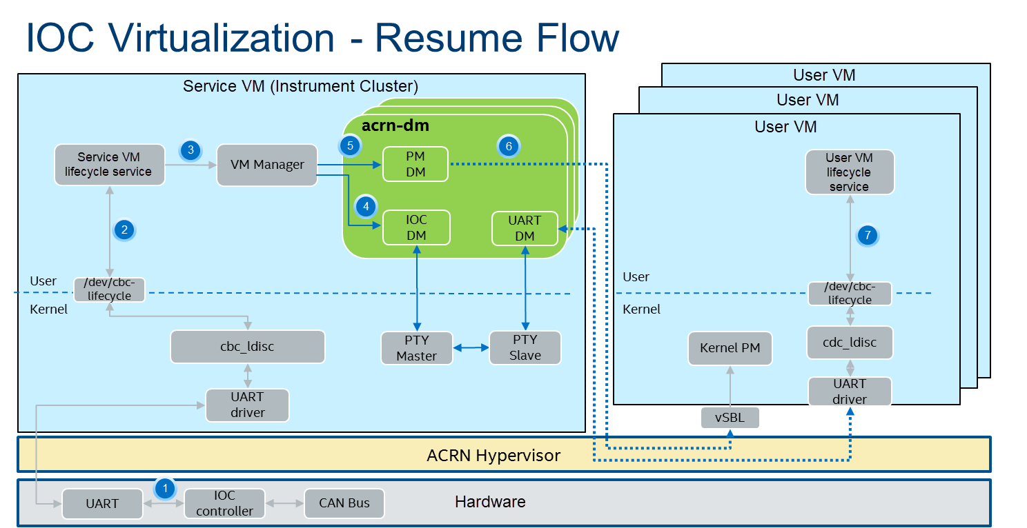
Figure 125 IOC Virtualizaton - Resume Flow
The resume reason contains both the ignition button and RTC, and has the same flow blocks.
For ignition resume flow:
Press ignition button to resume.
Service VM lifecycle service gets an initial wakeup reason from the IOC firmware. The wakeup reason is 0x000020, from which the ignition button bit is set. It then sends active or initial heartbeat to IOC firmware.
Service VM lifecycle forwards the wakeup reason and sends start event to VM Manager. The VM Manager starts to resume VMs.
IOC DM gets the wakeup reason from the VM Manager and forwards it to User VM lifecycle service.
VM Manager sets the VM state to starting for PM DM.
PM DM resumes User VM.
User VM lifecycle service gets wakeup reason 0x000020, and then sends an initial or active heartbeat. The User VM gets wakeup reason 0x800020 after resuming.
For RTC resume flow
RTC timer expires.
Service VM lifecycle service gets initial wakeup reason from the IOC firmware. The wakeup reason is 0x000200, from which RTC bit is set. It then sends active or initial heartbeat to IOC firmware.
Service VM lifecycle forwards the wakeup reason and sends start event to VM Manager. VM Manager begins resuming VMs.
IOC DM gets the wakeup reason from the VM Manager, and forwards it to the User VM lifecycle service.
VM Manager sets the VM state to starting for PM DM.
PM DM resumes User VM.
User VM lifecycle service gets the wakeup reason 0x000200, and sends initial or active heartbeat. The User VM gets wakeup reason 0x800200 after resuming.
System Control Data
IOC mediator has several emulated CBC commands, including wakeup reason, heartbeat, and RTC.
The wakeup reason, heartbeat, and RTC commands belong to the system control frames, which are used for startup or shutdown control. System control includes Wakeup Reasons, Heartbeat, Boot Selector, Suppress Heartbeat Check, and Set Wakeup Timer functions. Details are in this table:
System Control |
Value Name |
Description |
Data Direction |
|---|---|---|---|
1 |
Wakeup Reasons |
Wakeup Reasons |
IOC to SoC |
2 |
Heartbeat |
Heartbeat |
SoC to IOC |
3 |
Boot Selector |
Boot Selector |
SoC to IOC |
4 |
Suppress Heartbeat Check |
Suppress Heartbeat Check |
SoC to IOC |
5 |
Set Wakeup Timer |
Set Wakeup Timer in AIOC firmware |
SoC to IOC |
IOC mediator only supports wakeup reasons Heartbeat and Set Wakeup Timer.
The Boot Selector command is used to configure which partition the IOC has to use for normal and emergency boots. Additionally, the IOC has to report to the SoC after the CBC communication has been established successfully with which boot partition has been started and for what reason.
The Suppress Heartbeat Check command is sent by the SoC in preparation for maintenance tasks which requires the CBC Server to be shut down for a certain period of time. It instructs the IOC not to expect CBC heartbeat messages during the specified time. The IOC must disable any watchdog on the CBC heartbeat messages during this period of time.
Wakeup Reason
The wakeup reasons command contains a bit mask of all reasons, which is currently keeping the SoC/IOC active. The SoC itself also has a wakeup reason, which allows the SoC to keep the IOC active. The wakeup reasons should be sent every 1000 ms by the IOC.
Wakeup reason frame definition is as below:
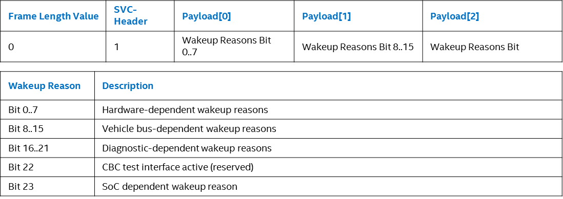
Figure 126 Wakeup Reason Frame Definition
Currently the wakeup reason bits are supported by sources shown here:
Wakeup Reason |
Bit |
Source |
|---|---|---|
wakeup_button |
5 |
Get from IOC firmware, forward to User VM |
RTC wakeup |
9 |
Get from IOC firmware, forward to User VM |
Car door wakeup |
11 |
Get from IOC firmware, forward to User VM |
SoC wakeup |
23 |
Emulation (Depends on User VM’s heartbeat message |
CBC_WK_RSN_BTN (bit 5): Ignition button.
CBC_WK_RSN_RTC (bit 9): RTC timer.
CBC_WK_RSN_DOR (bit 11): Car door.
CBC_WK_RSN_SOC (bit 23): SoC active/inactive.
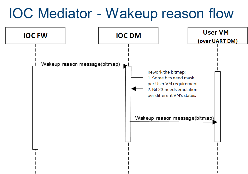
Figure 127 IOC Mediator - Wakeup Reason Flow
Bit 23 is for the SoC wakeup indicator and should not be forwarded directly because every VM has a different heartbeat status.
Heartbeat
The Heartbeat is used for SoC watchdog, indicating the SoC power reset behavior. Heartbeat needs to be sent every 1000 ms by the SoC.
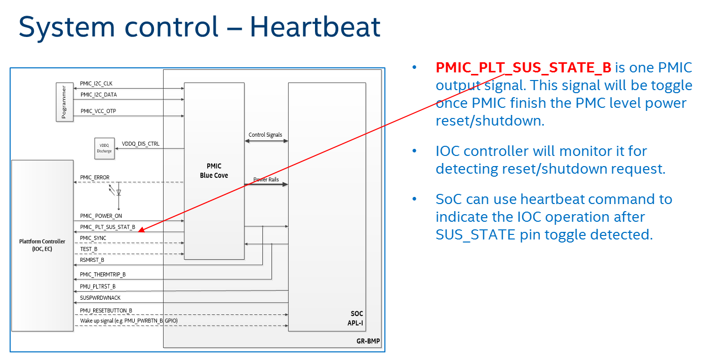
Figure 128 System Control - Heartbeat
Heartbeat frame definition is shown here:
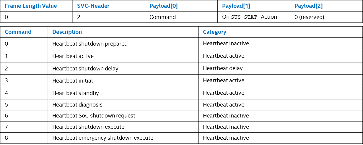
Figure 129 Heartbeat Frame Definition
Heartbeat active is repeatedly sent from SoC to IOC to signal that the SoC is active and intends to stay active. The On SUS_STAT action must be set to invalid.
Heartbeat inactive is sent once from SoC to IOC to signal that the SoC is ready for power shutdown. The On SUS_STAT action must be set to a required value.
Heartbeat delay is repeatedly sent from SoC to IOC to signal that the SoC has received the shutdown request, but isn’t ready for shutdown yet (for example, a phone call or other time consuming action is active). The On SUS_STAT action must be set to invalid.

Figure 130 Heartbeat Commands
SUS_STAT invalid action needs to be set with a heartbeat active message.
For the heartbeat inactive message, the SoC needs to be set from command 1 to 7 following the related scenarios. For example: S3 case needs to be set at 7 to prevent from power gating the memory.
The difference between halt and reboot is related if the power rail that supplies to customer peripherals (such as Fan, HDMI-in, BT/Wi-Fi, M.2, and Ethernet) is reset.
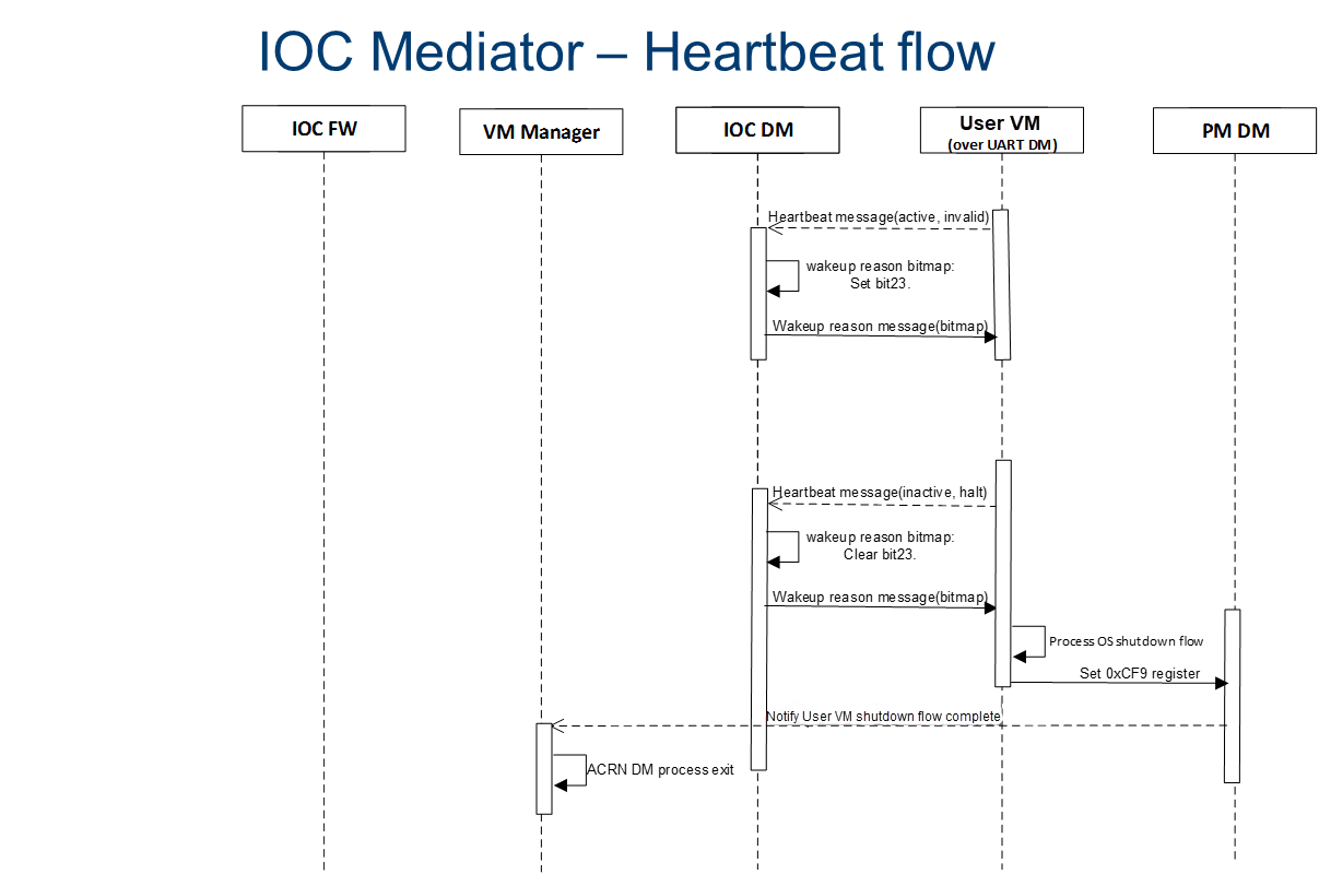
Figure 131 IOC Mediator - Heartbeat Flow
IOC DM will not maintain a watchdog timer for a heartbeat message. This is because it already has other watchdog features, so the main use of Heartbeat active command is to maintain the virtual wakeup reason bitmap variable.
For Heartbeat, IOC mediator supports Heartbeat shutdown prepared, Heartbeat active, Heartbeat shutdown delay, Heartbeat initial, and Heartbeat Standby.
For SUS_STAT, IOC mediator supports invalid action and RAM refresh action.
For Suppress heartbeat check will also be dropped directly.
RTC
RTC timer is used to wake up the SoC when the timer is expired. (A use case is for an automatic software upgrade with a specific time.) RTC frame definition is as below.
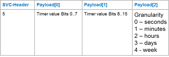
The RTC command contains a relative time but not an absolute time.
Service VM lifecycle service will re-compute the time offset before it is sent to the IOC firmware.
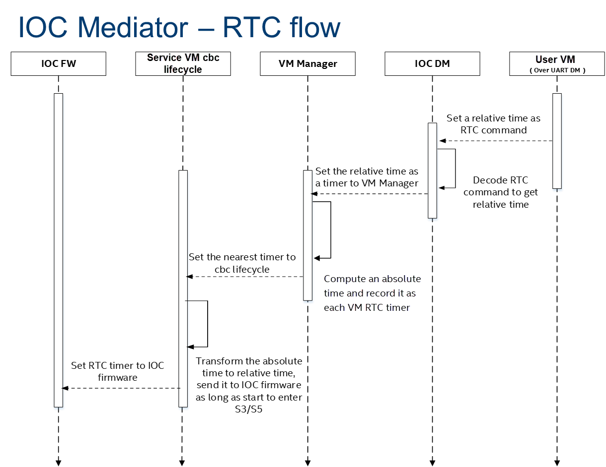
Figure 132 IOC Mediator - RTC Flow
Signal Data
Signal channel is an API between the SoC and IOC for miscellaneous requirements. The process data includes all vehicle bus and carrier board data (GPIO, sensors, and so on). It supports transportation of single signals and group signals. Each signal consists of a signal ID (reference), its value, and its length. IOC and SoC need agreement on the definition of signal IDs that can be treated as API interface definitions.
IOC signal type definitions are as below.
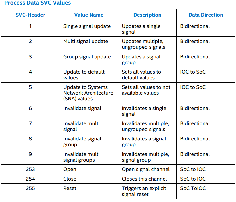
Figure 133 Process Data SVC Values
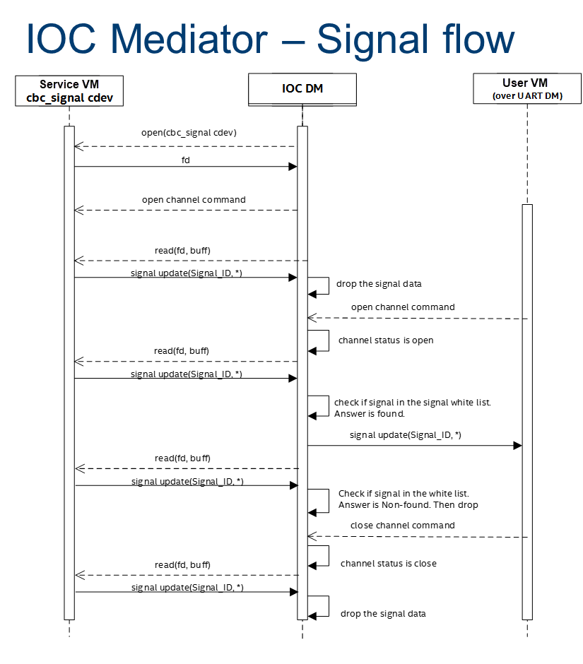
Figure 134 IOC Mediator - Signal Flow
The IOC backend needs to emulate the channel open/reset/close message which shouldn’t be forwarded to the native cbc signal channel. The Service VM signal related services should do a real open/reset/close signal channel.
Every backend should maintain a passlist for different VMs. The passlist can be stored in the Service VM file system (Read only) in the future, but currently it is hard coded.
IOC mediator has two passlist tables, one is used for rx signals (SoC->IOC), and the other one is used for tx signals. The IOC mediator drops the single signals and group signals if the signals are not defined in the passlist. For multi signal, IOC mediator generates a new multi signal, which contains the signals in the passlist.
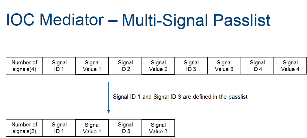
Figure 135 IOC Mediator - Multi-Signal Passlist
Raw Data
OEM raw channel only assigns to a specific User VM following that OEM configuration. The IOC Mediator will directly forward all read/write messages from IOC firmware to the User VM without any modification.
IOC Mediator Usage
The Device Model configuration command syntax for IOC mediator is as follows:
-i,[ioc_channel_path],[wakeup_reason]
-l,[lpc_port],[ioc_channel_path]
The ioc_channel_path is an absolute path for communication between
IOC mediator and UART DM.
The lpc_port is com1 or com2. IOC mediator needs one unassigned
lpc port for data transfer between User VM and Service VM.
The wakeup_reason is the IOC mediator boot reason. Each bit represents
one wakeup reason.
For example, the following commands are used to enable the IOC feature. The initial wakeup reason is the ignition button and cbc_attach uses ttyS1 for TTY line discipline in the User VM:
-i /run/acrn/ioc_$vm_name,0x20
-l com2,/run/acrn/ioc_$vm_name