Hypervisor Startup
This section is an overview of the ACRN hypervisor startup. The ACRN hypervisor compiles to a 32-bit multiboot-compliant ELF file. The bootloader (ABL/SBL or GRUB) loads the hypervisor according to the addresses specified in the ELF header. The bootstrap processor (BSP) starts the hypervisor with an initial state compliant to the multiboot 1 specification, after the bootloader prepares full configurations including ACPI, E820, etc.
The HV startup has two parts: the native startup followed by VM startup.
Multiboot Header
The ACRN hypervisor is built with a multiboot header, which presents
MULTIBOOT_HEADER_MAGIC and MULTIBOOT_HEADER_FLAGS at the beginning
of the image. It sets bit 6 in MULTIBOOT_HEADER_FLAGS, which requests the
bootloader pass memory map information (such as E820 entries) through the
Multiboot Information (MBI) structure.
Native Startup
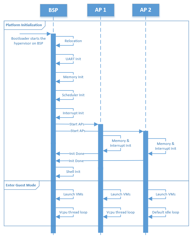
Figure 83 Hypervisor Native Startup Flow
Native startup sets up a baseline environment for HV, including basic memory and interrupt initialization as shown in Figure 83. Here is a short description for the flow:
BSP Startup: The starting point for the bootstrap processor.
Relocation: Relocate the hypervisor image if the hypervisor image is not placed at the assumed base address.
UART Init: Initialize a pre-configured UART device used as the base physical console for HV and Service VM.
Memory Init: Initialize memory type and cache policy, and create MMU page table mapping for HV.
Scheduler Init: Initialize the scheduler framework, which provides the capability to switch different threads (such as vcpu vs. idle thread) on a physical CPU, and to support CPU sharing.
Interrupt Init: Initialize interrupts and exceptions for native HV including IDT and
do_IRQinfrastructure; a timer interrupt framework is then built. The native/physical interrupts will go through thisdo_IRQinfrastructure then distribute to special targets (HV or VMs).Start AP: BSP triggers the
INIT-SIPI-SIPIIPI sequence to start other native APs (application processor). Each AP initializes its own memory and interrupts, notifies the BSP on completion, and enters the default idle loop.Shell Init: Start a command shell for HV accessible via the UART.
Symbols in the hypervisor are placed with an assumed base address, but the bootloader may not place the hypervisor at that specified base. In this case, the hypervisor will relocate itself to where the bootloader loads it.
Here is a summary of CPU and memory initial states that are set up after the native startup.
- CPU
ACRN hypervisor brings all physical processors to 64-bit IA32e mode, with the assumption that the BSP starts in protection mode where segmentation and paging sets an identical mapping of the first 4G addresses without permission restrictions. The control registers and some MSRs are set as follows:
cr0: The following features are enabled: paging, write protection, protection mode, numeric error and co-processor monitoring.cr3: Refer to the initial state of memory.cr4: The following features are enabled: physical address extension, machine-check, FXSAVE/FXRSTOR, SMEP, VMX operation and unmask SIMD FP exception. The other features are disabled.MSR_IA32_EFER: Only IA32e mode is enabled.MSR_IA32_FS_BASE: The address of stack canary, used for detecting stack smashing.MSR_IA32_TSC_AUX: A unique logical ID is set for each physical processor.stack: Each physical processor has a separate stack.
- Memory
All physical processors are in 64-bit IA32e mode after startup. The GDT holds four entries, one unused, one for code and another for data, both of which have a base of all 0’s and a limit of all 1’s, and the other for 64-bit TSS. The TSS only holds three stack pointers (for machine-check, double fault and stack fault) in the interrupt stack table (IST) which are different across physical processors. LDT is disabled.
Refer to Physical Interrupt Initialization for a detailed description of interrupt-related initial states, including IDT and physical PICs.
After the BSP detects that all APs are up, it continues to enter guest mode.
Likewise, after one AP completes its initialization, it starts entering guest
mode as well. When the BSP and APs enter guest mode, they try to launch
predefined VMs whose vBSP is associated with this physical core. These
predefined VMs are configured in vm config and may be a
pre-launched Safety VM or Service VM.
VM Startup
The Service VM or a pre-launched VM is created and launched on the physical CPU that is configured as its vBSP. Meanwhile, for the physical CPUs that are configured as vAPs for dedicated VMs, they enter the default idle loop (refer to vCPU Lifecycle for details), waiting for any vCPU to be scheduled to them.
Figure 84 illustrates a high-level execution flow of creating and launching a VM, applicable to pre-launched User VMs, Service VM, and post-launched User VMs. One major difference in the creation of post-launched User VMs vs. pre-launched User VMs or Service VM is that the pre-launched User VMs and Service VM are created by the hypervisor, while post-launched User VMs are created by the Device Model (DM) in the Service VM. The main steps include:
Create VM: A VM structure is allocated and initialized. A unique VM ID is picked, EPT is initialized, E820 table for this VM is prepared, I/O bitmap is set up, virtual PIC/IOAPIC/PCI/UART is initialized, EPC for virtual SGX is prepared, guest PM IO is set up, IOMMU for PT dev support is enabled, virtual CPUID entries are filled, and vCPUs configured in this VM’s
vm configare prepared. For a post-launched User VM, the EPT page table and E820 table are prepared by the DM instead of the hypervisor.Prepare vCPUs: Create the vCPUs, assign the physical processor that the vCPU is pinned to (a unique-per-VM vCPU ID and a globally unique VPID), initialize its virtual LAPIC and MTRR, and set up its vCPU thread object for vCPU scheduling. The vCPU number and affinity are defined in the corresponding
vm configfor this VM.Build vACPI: For the Service VM, the hypervisor customizes a virtual ACPI table based on the native ACPI table (this is in the TODO). For a pre-launched User VM, the hypervisor builds a simple ACPI table with necessary information such as MADT. For a post-launched User VM, the DM builds its ACPI table dynamically.
Software Load: Prepare for each VM’s software configuration according to guest OS requirements, which may include kernel entry address, ramdisk address, bootargs, or zero page for launching bzImage. This is done by the hypervisor for pre-launched User VMs or Service VM. The VM will start from the standard real mode or protected mode, which is not related to the native environment. For post-launched User VMs, the VM’s software configuration is done by DM.
Start VM: The vBSP of vCPUs in this VM is triggered to start scheduling.
Schedule vCPUs: The vCPUs are scheduled to the corresponding physical processors for execution.
Init VMCS: Initialize vCPU’s VMCS for its host state, guest state, execution control, entry control, and exit control. It’s the last configuration before vCPU runs.
vCPU thread: vCPU starts to run. For the vBSP of vCPUs, it will start running the configured kernel image. For any vAP of vCPUs, it will wait for the
INIT-SIPI-SIPIIPI sequence trigger from its vBSP.
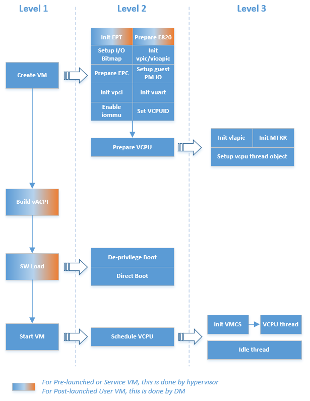
Figure 84 Hypervisor VM Startup Flow
Software configuration for Service VM (bzimage software load as example):
ACPI: HV passes the entire ACPI table from the bootloader to the Service VM directly. Legacy mode is supported as the ACPI table is loaded at F-Segment.
E820: HV passes the E820 table from the bootloader through the zero page after the HV reserved memory (32M, for example) and pre-launched User VM owned memory are filtered out.
Zero Page: HV prepares the zero page at the high end of Service VM memory, which is determined by the Service VM guest FIT binary build. The zero page includes the configuration for ramdisk, bootargs, and E820 entries. The zero page address will be set to the vBSP RSI register before the vCPU runs.
Entry address: HV copies the Service VM OS kernel image to
kernel_load_addr, which it can get from thepref_addrfield in the bzimage header. The entry address will be calculated based onkernel_load_addr, and will be set to the vBSP RIP register before the vCPU runs.
Software configuration for post-launched User VMs (OVMF software load as example):
ACPI: the DM builds the virtual ACPI table and puts it at the User VM’s F-Segment. Refer to I/O Emulation High-Level Design for details.
E820: the DM builds the virtual E820 table and passes it to the virtual bootloader. Refer to I/O Emulation High-Level Design for details.
Entry address: the DM copies the User VM OS kernel (OVMF) image to
OVMF_NVSTORAGE_OFFSET- normally is @(4G - 2M), and sets the entry address to 0xFFFFFFF0. As the vBSP will trigger the virtual bootloader (OVMF) to run from real mode, its CS base will be set to 0xFFFF0000, and RIP register will be set to 0xFFF0.
Software configuration for pre-launched User VMs (raw software load as example):
ACPI: the hypervisor builds the virtual ACPI table and puts it at this VM’s F-Segment.
E820: the hypervisor builds the virtual E820 table and passes it to the VM according to different software loaders. For a raw software load, it’s not used.
Entry address: the hypervisor copies the User VM OS kernel image to
kernel_load_addrwhich is set byvm config, and sets the entry address tokernel_entry_addrwhich is set byvm configas well.
Here is the initial mode of vCPUs:
VM and Processor Type |
Initial Mode |
|
|---|---|---|
Service VM |
BSP |
Same as physical BSP, or Real Mode if Service VM boots with OVMF |
AP |
Real Mode |
|
Post-launched User VM |
BSP |
Real Mode |
AP |
Real Mode |
|
Pre-launched User VM |
BSP |
Real Mode or Protected Mode |
AP |
Real Mode |
|