VT-d
Intel Virtual Technology for Directed I/O, or VT-d, provides hardware support for I/O device virtualization. It extends the protection and isolation properties of VMs for I/O operations.
VT-d provides the following main functions:
DMA remapping: for supporting address translations for DMA from devices.
Interrupt remapping: for supporting isolation and routing of interrupts from devices and external interrupt controllers to the appropriate VMs.
Interrupt posting: for supporting direct delivery of virtual interrupts from devices and external controllers to virtual processors.
The ACRN hypervisor supports DMA remapping that provides address translation capability for PCI passthrough devices, and second-level translation, which applies to requests-without-PASID. ACRN does not support First-level/nested translation.
DMAR Engines Discovery
DMA Remapping Report ACPI Table
For generic platforms, the ACRN hypervisor retrieves DMAR information from the ACPI table and then parses the DMAR reporting structure to discover the number of DMA-remapping hardware units present in the platform as well as the devices under the scope of a remapping hardware unit, as shown in Figure 184:
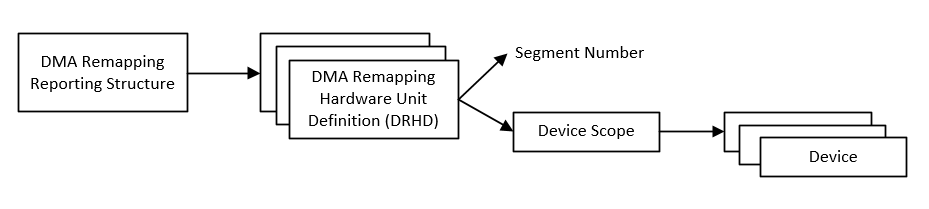
Figure 184 DMA Remapping Reporting Structure
Pre-Parsed DMAR Information
For specific platforms, the ACRN hypervisor uses pre-parsed DMA remapping reporting information directly to save hypervisor bootup time.
DMA Remapping
DMA remapping hardware is used to isolate device access to memory, enabling each device in the system to be assigned to a specific domain through a distinct set of paging structures.
Domains
A domain is abstractly defined as an isolated environment in the platform, to which a subset of the host physical memory is allocated. The memory resource of a domain is specified by the address translation tables.
Device to Domain Mapping Structure
VT-d hardware uses root-table and context-tables to build the mapping between devices and domains as shown in Figure 185.
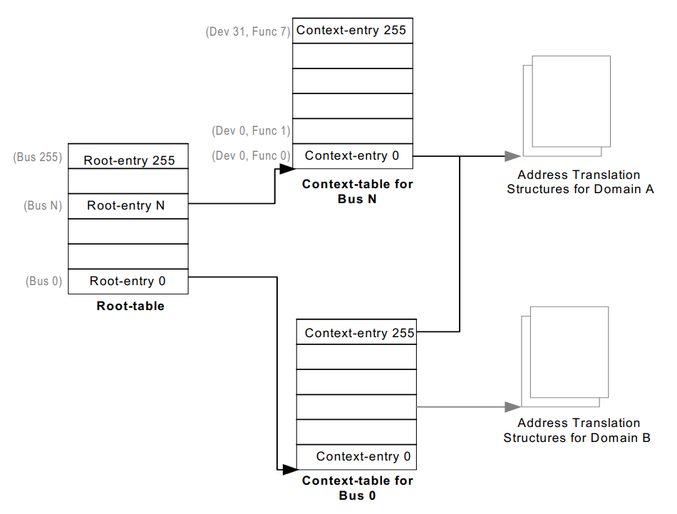
Figure 185 Device to Domain Mapping structures
The root-table is 4-KByte in size and contains 256 root-entries to cover the PCI bus number space (0-255). Each root-entry contains a context-table pointer to reference the context-table for devices on the bus identified by the root-entry, if the present flag of the root-entry is set.
Each context-table contains 256 entries, with each entry corresponding to a PCI device function on the bus. For a PCI device, the device and function numbers (8-bits) are used to index into the context-table. Each context-entry contains a Second-level Page-table Pointer, which provides the host physical address of the address translation structure in system memory to be used for remapping requests-without-PASID processed through the context-entry.
For a given Bus, Device, and Function combination as shown in Figure 186, a passthrough device can be associated with the address translation structures for a domain.
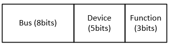
Figure 186 BDF Format of Passthrough Device
Refer to the VT-d spec for more details on device-to-domain mapping structures.
Address Translation Structures
For ACRN, the EPT table of a domain is used as the address translation structures for the devices assigned to the domain, as shown in Figure 187.
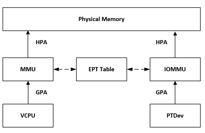
Figure 187 DMA Remapping Diagram
When the device attempts to access system memory, the DMA remapping hardware intercepts the access and utilizes the EPT table of the domain to determine whether the access is allowed. It then translates the DMA address according to the EPT table from the guest physical address (GPA) to the host physical address (HPA).
Domains and Memory Isolation
DMA operations do not exist inside the hypervisor, so ACRN doesn’t create a domain for the hypervisor. No DMA operations from passthrough devices can access the hypervisor memory.
ACRN treats each virtual machine (VM) as a separate domain. For a VM, an EPT table exists for Normal world; an EPT table for Secure world might also exist. Secure world can access Normal world’s memory, but Normal world cannot access Secure world’s memory.
- SOS_VM domain
The SOS_VM domain is created when the hypervisor creates the VM for the Service OS.
IOMMU uses the EPT table of Normal world of SOS_VM as the address translation structures for the devices in the SOS_VM domain. The Normal world’s EPT table of SOS_VM doesn’t include the memory resource of the hypervisor and Secure worlds (if any exists). So the devices in SOS_VM domain can’t access the memory belonging to the hypervisor or secure worlds.
- Other domains
Other VM domains will be created when the hypervisor creates the User OS. One domain for each User OS.
IOMMU uses the EPT table of the Normal world of a VM as the address translation structures for the devices in the domain. The Normal world’s EPT table of the VM only allows devices to access the memory allocated for the Normal world of the VM.
Page-Walk Coherency
For the VT-d hardware, which doesn’t support page-walk coherency, the hypervisor needs to make sure the updates of VT-d tables are synced in memory:
Device to Domain Mapping Structures, including Root-entries and Context-entries.
The EPT table of a VM.
ACRN flushes the related cache line after these structures are updated if the VT-d hardware doesn’t support page-walk coherency.
Super-Page Support
The ACRN VT-d reuses the EPT table as the address translation table. VT-d capability or super-page support should be identical with the usage of the EPT table.
Snoop Control
If VT-d hardware supports snoop control, iVT-d can control the ability to ignore the “no-snoop attribute” in PCI-E transactions.
The following table shows the snoop behavior of a DMA operation controlled by the following:
Snoop Control capability of VT-d DMAR unit
The setting of SNP filed in leaf PTE
No-snoop attribute in PCI-e request
SC cap of VT-d |
SNP filed in leaf PTE |
No-snoop attribute in request |
Snoop behavior |
|---|---|---|---|
0 |
0 (must be 0) |
no snoop |
No snoop |
0 |
0 (must be 0) |
snoop |
Snoop |
1 |
1 |
snoop / no snoop |
Snoop |
1 |
0 |
no snoop |
No snoop |
1 |
0 |
snoop |
Snoop |
If VT-d DMAR units do not support Snoop Control, then the SNP Bit (bit 11) of leaf PETs of the EPT is not set since the field is treated as reserved (0) by the VT-d hardware implementations of not supporting Snoop Control.
The VT-d DMAR unit of the Intel integrated graphics device doesn’t support Snoop Control. The ACRN hypervisor uses the same copy of EPT as the secondary address translation table for a VM. When the DMAR unit for the Intel integrated graphics device is enabled, the SNP Bit cannot be set in the lead PTEs of the EPT.
No matter if ACRN enables or disables Snoop Control, the DMA operations of passthrough devices behave correctly from the guest’s point of view. ACRN disables Snoop Control in VT-d DMAR engines that simplify the implementation. Also, since the snoop behavior of PCIE transactions can be controlled by guest drivers, some devices may take advantage of the NO_SNOOP_ATTRIBUTE of PCIE transactions for better performance when snoop is not needed.
The driver is responsible for configuring correct attribute in PCIE transactions. Otherwise, the corresponding device may not work properly.
Initialization
During hypervisor initialization, it registers DMAR units on the platform according to the reparsed information or DMAR table. There may be multiple DMAR units on the platform, ACRN allows some of the DMAR units to be ignored. If some DMAR unit(s) are marked as ignored, they would not be enabled.
Hypervisor creates SOS_VM domain using the Normal World’s EPT table of SOS_VM as address translation table when creating SOS_VM as Service OS. And all PCI devices on the platform are added to SOS_VM domain. Then enable DMAR translation for DMAR unit(s) if they are not marked as ignored.
Device Assignment
All devices are initially added to the SOS_VM domain. To assign a device means to assign the device to a User VM. The device is removed from the SOS_VM domain and is added to the VM domain related to the User VM, which changes the address translation table from the EPT of SOS_VM to the EPT of the User OS for the device.
To unassign a device means to unassign the device from a User OS. The device is removed from the VM domain related to the User OS and then added back to the SOS_VM domain; this changes the address translation table from the EPT of the User OS to the EPT of the SOS_VM for the device.
Power Management Support for S3
During platform S3 suspend and resume, the VT-d register values are lost. ACRN VT-d provides APIs that are called during S3 suspend and resume.
During S3 suspend, some register values are saved in the memory, and DMAR translation is disabled. During S3 resume, the register values saved are restored. The Root table address register is set. The DMAR translation is enabled.
All operations for S3 suspend and resume are performed on all DMAR units on the platform, except for the DMAR units marked ignored.
Error Handling
ACRN VT-d supports DMA remapping error reporting. ACRN VT-d requests a IRQ / vector for DMAR error reporting. A DMAR fault handler is registered for the IRQ. DMAR unit supports report fault event via MSI. When a fault event occurs, a MSI is generated, so that the DMAR fault handler will be called to report the error event.
Data Structures and Interfaces
Initialization and Deinitialization
The following APIs are provided during initialization and deinitialization:
-
int32_t
init_iommu(void)¶ Init IOMMUs.
Register DMAR units on the platform according to the pre-parsed information or DMAR table. IOMMU is a must have feature, if init_iommu failed, the system should not continue booting.
- Return Value
0: on success<0: on failure
Runtime
The following API are provided during runtime:
-
struct iommu_domain *
create_iommu_domain(uint16_t vm_id, uint64_t translation_table, uint32_t addr_width)¶ Create a iommu domain for a VM specified by vm_id.
Create a iommu domain for a VM specified by vm_id, along with address translation table and address width.
- Return
Pointer to the created iommu_domain
- Preconditions
vm_id is valid
- Preconditions
translation_table != 0
- Parameters
[in] vm_id: vm_id of the VM the domain created for[in] translation_table: the physcial address of EPT table of the VM specified by the vm_id[in] addr_width: address width of the VM
- Return Value
NULL: whentranslation_tableis 0!NULL: whentranslation_tableis not 0
-
void
destroy_iommu_domain(struct iommu_domain *domain)¶ Destroy the specific iommu domain.
Destroy the specific iommu domain when a VM no longer needs it.
- Preconditions
domain != NULL
- Parameters
[in] domain: iommu domain to destroy
-
void
suspend_iommu(void)¶ Suspend IOMMUs.
Suspend all IOMMUs, which are not ignored on the platform.
-
void
resume_iommu(void)¶ Resume IOMMUs.
Resume all IOMMUs, which are not ignored on the platform.
-
int32_t
move_pt_device(const struct iommu_domain *from_domain, const struct iommu_domain *to_domain, uint8_t bus, uint8_t devfun)¶ Assign a device specified by bus & devfun to a iommu domain.
Remove the device from the from_domain (if non-NULL), and add it to the to_domain (if non-NULL). API silently fails to add/remove devices to/from domains that are under “Ignored” DMAR units.
- Preconditions
domain != NULL
- Parameters
[in] from_domain: iommu domain from which the device is removed from[in] to_domain: iommu domain to which the device is assgined to[in] bus: the 8-bit bus number of the device[in] devfun: the 8-bit device(5-bit):function(3-bit) of the device
- Return Value
0: on success.1: fail to unassign the device