Physical Interrupt high-level design
Overview
The ACRN hypervisor implements a simple but fully functional framework to manage interrupts and exceptions, as show in Figure 88. In its native layer, it configures the physical PIC, IOAPIC, and LAPIC to support different interrupt sources from local timer/IPI to external INTx/MSI. In its virtual guest layer, it emulates virtual PIC, virtual IOAPIC and virtual LAPIC, and provides full APIs allowing virtual interrupt injection from emulated or pass-thru devices.
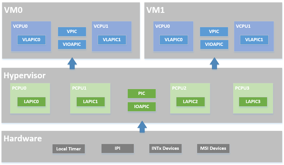
Figure 88 ACRN Interrupt Modules Overview
In the software modules view shown in Figure 89, the ACRN hypervisor sets up the physical interrupt in its basic interrupt modules (e.g., IOAPIC/LAPIC/IDT). It dispatches the interrupt in the hypervisor interrupt flow control layer to the corresponding handlers, that could be pre-defined IPI notification, timer, or runtime registered pass-thru devices. The ACRN hypervisor then uses its VM interfaces based on vPIC, vIOAPIC, and vMSI modules, to inject the necessary virtual interrupt into the specific VM
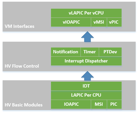
Figure 89 ACRN Interrupt SW Modules Overview
The hypervisor implements the following functionalities for handling physical interrupts:
- Configure interrupt-related hardware including IDT, PIC, LAPIC, and IOAPIC on startup.
- Provide APIs to manipulate the registers of LAPIC and IOAPIC.
- Acknowledge physical interrupts.
- Set up a callback mechanism for the other components in the hypervisor to request for an interrupt vector and register a handler for that interrupt.
HV owns all native physical interrupts and manages 256 vectors per CPU. All physical interrupts are first handled in VMX root-mode. The “external-interrupt exiting” bit in VM-Execution controls field is set to support this. The ACRN hypervisor also initializes all the interrupt related modules like IDT, PIC, IOAPIC, and LAPIC.
HV does not own any host devices (except UART). All devices are by default assigned to SOS. Any interrupts received by Guest VM (SOS or UOS) device drivers are virtual interrupts injected by HV (via vLAPIC). HV manages a Host-to-Guest mapping. When a native IRQ/interrupt occurs, HV decides whether this IRQ/interrupt should be forwarded to a VM and which VM to forward to (if any). Refer to section 3.7.6 for virtual interrupt injection and section 3.9.6 for the management of interrupt remapping.
HV does not own any exceptions. Guest VMCS are configured so no VM Exit happens, with some exceptions such as #INT3 and #MC. This is to simplify the design as HV does not support any exception handling itself. HV supports only static memory mapping, so there should be no #PF or #GP. If HV receives an exception indicating an error, an assert function is then executed with an error message print out, and the system then halts.
Native interrupts could be generated from one of the following sources:
- GSI interrupts
- PIC or Legacy devices IRQ (0~15)
- IOAPIC pin
- PCI MSI/MSI-X vectors
- Inter CPU IPI
- LAPIC timer
Physical Interrupt Initialization
After ACRN hypervisor gets control from the bootloader, it initializes all physical interrupt-related modules for all the CPUs. ACRN hypervisor creates a framework to manage the physical interrupt for hypervisor local devices, pass-thru devices, and IPI between CPUs, as shown in Figure 90:
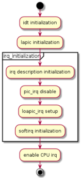
Figure 90 Physical Interrupt Initialization
IDT Initialization
ACRN hypervisor builds its native IDT (interrupt descriptor table) during interrupt initialization and set up the following handlers:
- On an exception, the hypervisor dumps its context and halts the current physical processor (because physical exceptions are not expected).
- For external interrupts, HV may mask the interrupt (depending on the trigger mode), followed by interrupt acknowledgement and dispatch to the registered handler, if any.
Most interrupts and exceptions are handled without a stack switch, except for machine-check, double fault, and stack fault exceptions which have their own stack set in TSS.
PIC/IOAPIC Initialization
ACRN hypervisor masks all interrupts from the PIC. All legacy interrupts from PIC (<16) will be linked to IOAPIC, as shown in the connections in Figure 91.
ACRN will pre-allocate vectors and mask them for these legacy interrupt in IOAPIC RTE. For others (>= 16), ACRN will mask them with vector 0 in RTE, and the vector will be dynamically allocate on demand.
All external IOAPIC pins are categorized as GSI interrupt according to ACPI definition. HV supports multiple IOAPIC components. IRQ PIN to GSI mappings are maintained internally to determine GSI source IOAPIC. Native PIC is not used in the system.
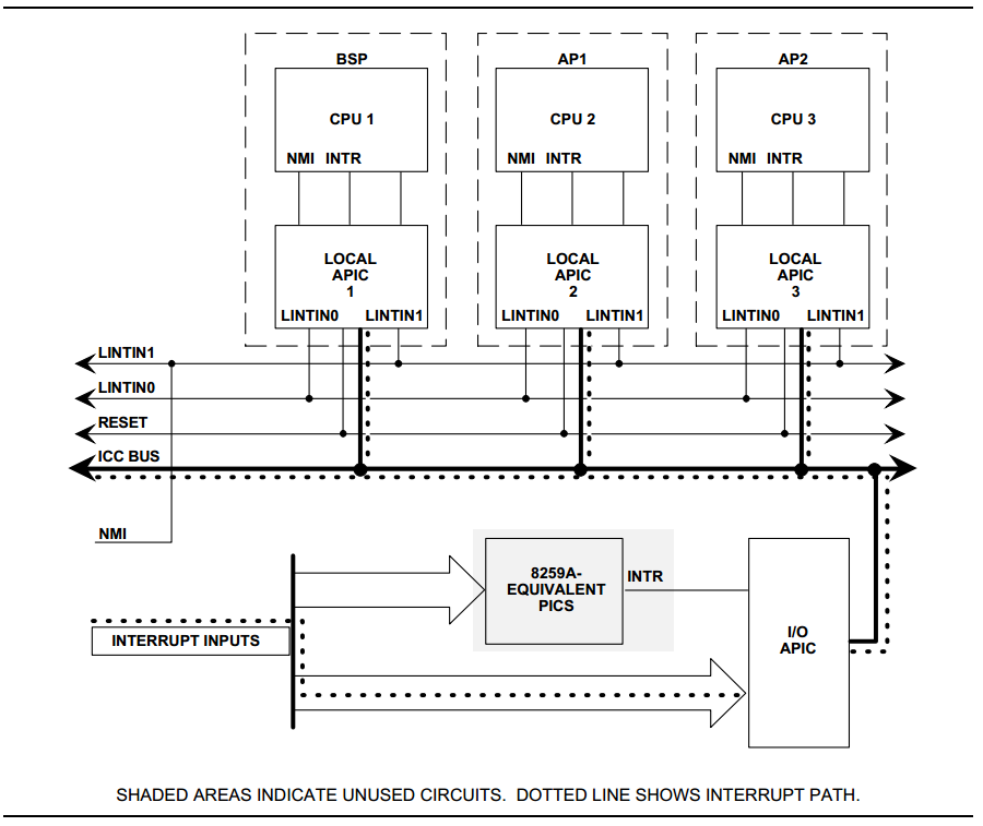
Figure 91 HV PIC/IOAPIC/LAPIC configuration
LAPIC Initialization
Physical LAPICs are in xAPIC mode in ACRN hypervisor. The hypervisor initializes LAPIC for each physical CPU by masking all interrupts in the local vector table (LVT), clearing all ISRs, and enabling LAPIC.
APIs are provided to access LAPIC for the other components in the hypervisor, aiming for further usage of local timer (TSC Deadline) program, IPI notification program, etc. See Data structures and interfaces for a complete list.
HV Interrupt Vectors and Delivery Mode
The interrupt vectors are assigned as shown here:
- Vector 0-0x1F
- are exceptions that are not handled by HV. If such an exception does occur, the system then halts.
- Vector: 0x20-0x2F
- are allocated statically for legacy IRQ0-15.
- Vector: 0x30-0xDF
- are dynamically allocated vectors for PCI devices INTx or MSI/MIS-X usage. According to different interrupt delivery mode (FLAT or PER_CPU mode), an interrupt will be assigned to a vector for all the CPUs or a particular CPU.
- Vector: 0xE0-0xFE
- are high priority vectors reserved by HV for dedicated purposes. For example, 0xEF is used for timer, 0xF0 is used for IPI.
| Vectors | Usage |
|---|---|
| 0x0-0x13 | Exceptions: NMI, INT3, page dault, GP, debug. |
| 0x14-0x1F | Reserved |
| 0x20-0x2F | Statically allocated for external IRQ (IRQ0-IRQ15) |
| 0x30-0xDF | Dynamically allocated for IOAPIC IRQ from PCI INTx/MSI |
| 0xE0-0xFE | Static allocated for HV |
| 0xEF | Timer |
| 0xF0 | IPI |
| 0xFF | SPURIOUS_APIC_VECTOR |
Interrupts from either IOAPIC or MSI can be delivered to a target CPU. By default they are configured as Lowest Priority (FLAT mode), i.e. they are delivered to a CPU core that is currently idle or executing lowest priority ISR. There is no guarantee a device’s interrupt will be delivered to a specific Guest’s CPU. Timer interrupts are an exception - these are always delivered to the CPU which programs the LAPIC timer.
There are two interrupt delivery modes: FLAT mode and PER_CPU mode. ACRN uses FLAT MODE where the interrupt/irq to vector mapping is the same on all CPUs. Every CPU receives same interrupts. IOAPIC and LAPIC MSI delivery mode are configured to Lowest Priority.
Vector allocation for CPUs is shown here:
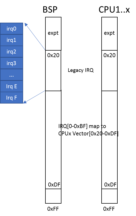
Figure 92 FLAT mode vector allocation
IRQ Descriptor Table
ACRN hypervisor maintains a global IRQ Descriptor Table shared among the physical CPUs. ACRN use FLAT MODE to manage the interrupts so the same vector will link to same the IRQ number for all CPUs.
Note
need to reference API doc for irq_desc
The irq_desc[] array’s index represents IRQ number. An irq_handler field could be set to common edge/level/quick handler which will be called from interrupt_dispatch. The irq_desc structure also contains the dev_list field to maintain this IRQ’s action handler list.
Another reverse mapping from vector to IRQ is used in addition to the IRQ descriptor table which maintains the mapping from IRQ to vector.
On initialization, the descriptor of the legacy IRQs are initialized with proper vectors and the corresponding reverse mapping is set up. The descriptor of other IRQs are filled with an invalid vector which will be updated on IRQ allocation.
For example, if local timer registers an interrupt with IRQ number 271 and vector 0xEF, then this date will be set up:
irq_desc[271].irq = 271
irq_desc[271].vector = 0xEF
vector_to_irq[0xEF] = 271
External Interrupt Handling
CPU runs under VMX non-root mode and inside Guest VMs.
MSR_IA32_VMX_PINBASED_CTLS.bit[0] and
MSR_IA32_VMX_EXIT_CTLS.bit[15] are set to allow vCPU VM Exit to HV
whenever there are interrupts to that physical CPU under
non-root mode. HV ACKs the interrupts in VMX non-root and saves the
interrupt vector to the relevant VM Exit field for HV IRQ processing.
Note that as discussed above, an external interrupt causing vCPU VM Exit to HV does not mean that the interrupt belongs to that Guest VM. When CPU executes VM Exit into root-mode, interrupt handling will be enabled and the interrupt will be delivered and processed as quickly as possible inside HV. HV may emulate a virtual interrupt and inject to Guest if necessary.
When an physical interrupt happened on a CPU, this CPU could be running under VMX root mode or non-root mode. If the CPU is running under VMX root mode, the interrupt is triggered from standard native IRQ flow - interrupt gate to IRQ handler. If the CPU is running under VMX non-root mode, an external interrupt will trigger a VM exit for reason “external-interrupt”.
Interrupt and IRQ processing flow diagrams are shown below:

Figure 93 Processing of physical interrupts
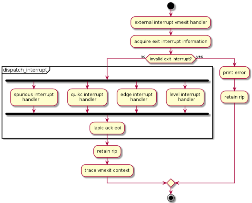
Figure 94 IRQ processing control flow
When a physical interrupt is raised and delivered to a physical CPU, the CPU may be running under either VMX root mode or non-root mode.
- If the CPU is running under VMX root mode, the interrupt is handled following the standard native IRQ flow: interrupt gate to dispatch_interrupt(), IRQ handler, and finally the registered callback.
- If the CPU is running under VMX non-root mode, an external interrupt calls a VM exit for reason “external-interrupt”, and then the VM exit processing flow will call dispatch_interrupt() to dispatch and handle the interrupt.
After an interrupt occurs from either path shown in Figure 93, ACRN hypervisor will jump to dispatch_interrupt. This function gets the vector of the generated interrupt from the context, gets IRQ number from vector_to_irq[], and then gets the corresponding irq_desc.
Though there is only one generic IRQ handler for registered interrupt, there are three different handling flows according to flags:
!IRQF_LEVELIRQF_LEVEL && !IRQF_PTTo avoid continuous interrupt triggers, it masks the IOAPIC pin and unmask it only after IRQ action callback is executed
IRQF_LEVEL && IRQF_PTFor pass-thru devices, to avoid continuous interrupt triggers, it masks the IOAPIC pin and leaves it unmasked until corresponding vIOAPIC pin gets an explicit EOI ACK from guest.
Since interrupts are not shared for multiple devices, there is only one IRQ action registered for each interrupt
The IRQ number inside HV is a software concept to identify GSI and Vectors. Each GSI will be mapped to one IRQ. The GSI number is usually the same as the IRQ number. IRQ numbers greater than max GSI (nr_gsi) number are dynamically assigned. For example, HV allocates an interrupt vector to a PCI device, an IRQ number is then assigned to that vector. When the vector later reaches a CPU, the corresponding IRQ routine is located and executed.
See Figure 95 for request IRQ control flow for different conditions:
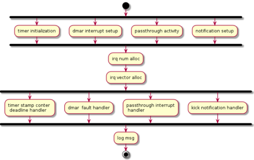
Figure 95 Request IRQ for different conditions
IPI Management
The only purpose of IPI use in HV is to kick a vCPU out of non-root mode and enter to HV mode. This requires I/O request and virtual interrupt injection be distributed to different IPI vectors. The I/O request uses IPI vector 0xF4 upcall (refer to Chapter 5.4). The virtual interrupt injection uses IPI vector 0xF0.
- 0xF4 upcall
- A Guest vCPU VM Exit exits due to EPT violation or IO instruction trap. It requires Device Module to emulate the MMIO/PortIO instruction. However it could be that the Service OS (SOS) vCPU0 is still in non-root mode. So an IPI (0xF4 upcall vector) should be sent to the physical CPU0 (with non-root mode as vCPU0 inside SOS) to force vCPU0 to VM Exit due to the external interrupt. The virtual upcall vector is then injected to SOS, and the vCPU0 inside SOS then will pick up the IO request and do emulation for other Guest.
- 0xF0 IPI flow
- If Device Module inside SOS needs to inject an interrupt to other Guest such as vCPU1, it will issue an IPI first to kick CPU1 (assuming CPU1 is running on vCPU1) to root-hv_interrupt-data-apmode. CPU1 will inject the interrupt before VM Enter.
Data structures and interfaces
IOAPIC
The following APIs are external interfaces for IOAPIC related operations.
void ioapic_get_rte(uint32_t irq, union ioapic_rte *rte)
   /*   get the redirection table entry of an irq. */

void ioapic_set_rte(uint32_t irq, union ioapic_rte rte)
   /*   Set the redirection table entry of an irq. */

uint32_t pin_to_irq(uint8_t pin)
   /*   Get irq num from physical irq pin num */

void suspend_ioapic(void)
   /*   Suspended ioapic, mainly save the RTEs. */

void resume_ioapic(void)
   /*   Resume ioapic, mainly restore the RTEs. */

int get_ioapic_info(char *str_arg, int str_max_len)
   /*   Dump information of ioapic for debug, such as irq num, pin,
    *   RTE, vector, trigger mode etc. For debugging only.
    */
LAPIC
The following APIs are external interfaces for LAPIC related operations.
void write_lapic_reg32(uint32_t offset, uint32_t value)
   /*   Write to lapic register. */

void early_init_lapic(void)
   /*   To get the local apic base addr, map lapic registers and check the
    *   xAPIC/x2APIC capability.
    */

void save_lapic(struct lapic_regs *regs)
   /*   Save context of lapic before entering s3. */

void restore_lapic(struct lapic_regs *regs)
   /*   Restore context of lapic when resume from s3. */

void resume_lapic(void)
   /*   Resume lapic by setting the apic base addr and restore the registers. */

uint8_t get_cur_lapic_id(void)
   /*   Get the lapic id. */
IPI
The following APIs are external interfaces for IPI related operations.
void send_startup_ipi(enum intr_cpu_startup_shorthand cpu_startup_shorthand,
                      uint16_t dest_pcpu_id, uint64_t cpu_startup_start_address)
   /*   Send an SIPI to a specific cpu, to notify the cpu to start booting. */

void send_dest_ipi(uint32_t dest, uint32_t vector, uint32_t dest_mode)
   /*   Send an IPI to a specific cpu with dest mode specified. */

void send_single_ipi(uint16_t pcpu_id, uint32_t vector)
   /*   Send an IPI to a specific cpu with physical dest mode. */
Physical Interrupt
The following APIs are external interfaces for physical interrupt related operations.
int32_t request_irq(uint32_t req_irq, irq_action_t action_fn, void *priv_data,
                    uint32_t flags)
   /*   Request interrupt num if not specified, and register irq action for the
    *   specified/allocated irq.
    */

void free_irq(uint32_t irq)
   /*   Free irq num and unregister the irq action. */

void set_irq_trigger_mode(uint32_t irq, bool is_level_triggered)
   /*   Set the irq trigger mode: edge-triggered or level-triggered */

uint32_t irq_to_vector(uint32_t irq)
   /*  Convert irq num to vector */

void get_cpu_interrupt_info(char *str_arg, int str_max)
   /*  To dump interrupt statistics info, such as irq num, vector,
    *  irq count on each physical cpu.
    */

void dispatch_interrupt(struct intr_excp_ctx *ctx)
   /*  To dispatch an interrupt, an action callback will be called if registered. */

void interrupt_init(uint16_t pcpu_id)
   /*  To do interrupt initialization for a cpu, will be called for
    *  each physical cpu.
    */