GVT-g high-level design
Introduction
Purpose of this Document
This high-level design (HLD) document describes the usage requirements and high level design for Intel® Graphics Virtualization Technology for shared virtual GPU technology (GVT-g) on Apollo Lake-I SoCs.
This document describes:
- The different GPU virtualization techniques
- GVT-g mediated pass-through
- High level design
- Key components
- GVT-g new architecture differentiation
Audience
This document is for developers, validation teams, architects and maintainers of Intel® GVT-g for the Apollo Lake SoCs.
The reader should have some familiarity with the basic concepts of system virtualization and Intel® processor graphics.
Reference Documents
The following documents were used as references for this specification:
- Paper in USENIX ATC ‘14 - Full GPU Virtualization Solution with Mediated Pass-Through - https://www.usenix.org/node/183932
- Hardware Specification - PRMs - https://01.org/linuxgraphics/documentation/hardware-specification-prms
Background
Intel® GVT-g is an enabling technology in emerging graphics virtualization scenarios. It adopts a full GPU virtualization approach based on mediated pass-through technology, to achieve good performance, scalability and secure isolation among Virtual Machines (VMs). A virtual GPU (vGPU), with full GPU features, is presented to each VM so that a native graphics driver can run directly inside a VM.
Intel® GVT-g technology for Apollo Lake (APL) has been implemented in open source hypervisors or Virtual Machine Monitors (VMMs):
- Intel® GVT-g for ACRN, also known as, “AcrnGT”
- Intel® GVT-g for KVM, also known as, “KVMGT”
- Intel® GVT-g for Xen, also known as, “XenGT”
The core vGPU device model is released under BSD/MIT dual license, so it can be reused in other proprietary hypervisors.
Intel has a portfolio of graphics virtualization technologies (GVT-g, GVT-d and GVT-s). GVT-d and GVT-s are outside of the scope of this document.
This HLD applies to the Apollo Lake platform only. Support of other hardware is outside the scope of this HLD.
Targeted Usages
The main targeted usage of GVT-g is in automotive applications, such as:
- An Instrument cluster running in one domain
- An In Vehicle Infotainment (IVI) solution running in another domain
- Additional domains for specific purposes, such as Rear Seat Entertainment or video camera capturing.
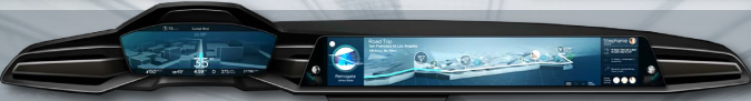
Figure 94 IVE Use Case
Existing Techniques
A graphics device is no different from any other I/O device, with respect to how the device I/O interface is virtualized. Therefore, existing I/O virtualization techniques can be applied to graphics virtualization. However, none of the existing techniques can meet the general requirement of performance, scalability, and secure isolation simultaneously. In this section, we review the pros and cons of each technique in detail, enabling the audience to understand the rationale behind the entire GVT-g effort.
Emulation
A device can be emulated fully in software, including its I/O registers and internal functional blocks. There would be no dependency on the underlying hardware capability, therefore compatibility can be achieved across platforms. However, due to the CPU emulation cost, this technique is usually used for legacy devices, such as a keyboard, mouse, and VGA card. There would be great complexity and extremely low performance to fully emulate a modern accelerator, such as a GPU. It may be acceptable for use in a simulation environment, but it is definitely not suitable for production usage.
API Forwarding
API forwarding, or a split driver model, is another widely-used I/O virtualization technology. It has been used in commercial virtualization productions, for example, VMware*, PCoIP*, and Microsoft* RemoteFx*. It is a natural path when researchers study a new type of I/O virtualization usage, for example, when GPGPU computing in VM was initially proposed. Intel® GVT-s is based on this approach.
The architecture of API forwarding is shown in Figure 95:
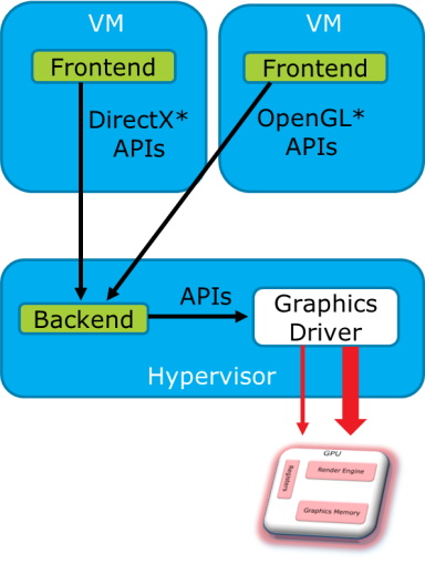
Figure 95 API Forwarding
A frontend driver is employed to forward high-level API calls (OpenGL, Directx, and so on) inside a VM, to a Backend driver in the Hypervisor for acceleration. The Backend may be using a different graphics stack, so API translation between different graphics protocols may be required. The Backend driver allocates a physical GPU resource for each VM, behaving like a normal graphics application in a Hypervisor. Shared memory may be used to reduce memory copying between the host and guest graphic stacks.
API forwarding can bring hardware acceleration capability into a VM, with other merits such as vendor independence and high density. However, it also suffers from the following intrinsic limitations:
- Lagging features - Every new API version needs to be specifically handled, so it means slow time-to-market (TTM) to support new standards. For example, only DirectX9 is supported, when DirectX11 is already in the market. Also, there is a big gap in supporting media and compute usages.
- Compatibility issues - A GPU is very complex, and consequently so are high level graphics APIs. Different protocols are not 100% compatible on every subtle API, so the customer can observe feature/quality loss for specific applications.
- Maintenance burden - Occurs when supported protocols and specific versions are incremented.
- Performance overhead - Different API forwarding implementations exhibit quite different performance, which gives rise to a need for a fine-grained graphics tuning effort.
Direct Pass-Through
“Direct pass-through” dedicates the GPU to a single VM, providing full features and good performance, but at the cost of device sharing capability among VMs. Only one VM at a time can use the hardware acceleration capability of the GPU, which is a major limitation of this technique. However, it is still a good approach to enable graphics virtualization usages on Intel server platforms, as an intermediate solution. Intel® GVT-d uses this mechanism.
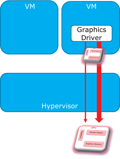
Figure 96 Pass-Through
SR-IOV
Single Root IO Virtualization (SR-IOV) implements I/O virtualization directly on a device. Multiple Virtual Functions (VFs) are implemented, with each VF directly assignable to a VM.
Mediated Pass-Through
Intel® GVT-g achieves full GPU virtualization using a “mediated pass-through” technique.
Concept
Mediated pass-through allows a VM to access performance-critical I/O resources (usually partitioned) directly, without intervention from the hypervisor in most cases. Privileged operations from this VM are trapped-and-emulated to provide secure isolation among VMs.
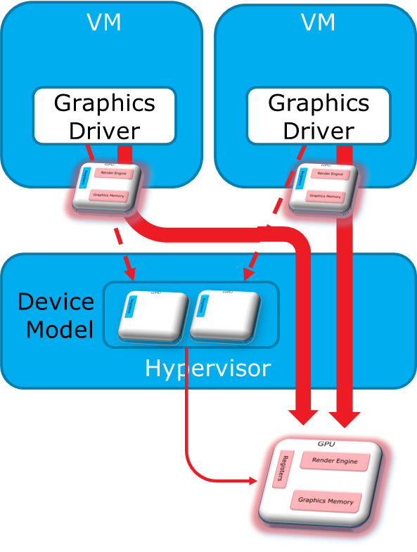
Figure 97 Mediated Pass-Through
The Hypervisor must ensure that no vulnerability is exposed when assigning performance-critical resource to each VM. When a performance-critical resource cannot be partitioned, a scheduler must be implemented (either in software or hardware) to allow time-based sharing among multiple VMs. In this case, the device must allow the hypervisor to save and restore the hardware state associated with the shared resource, either through direct I/O register reads and writes (when there is no software invisible state) or through a device-specific context save and restore mechanism (where there is a software invisible state).
Examples of performance-critical I/O resources include the following:
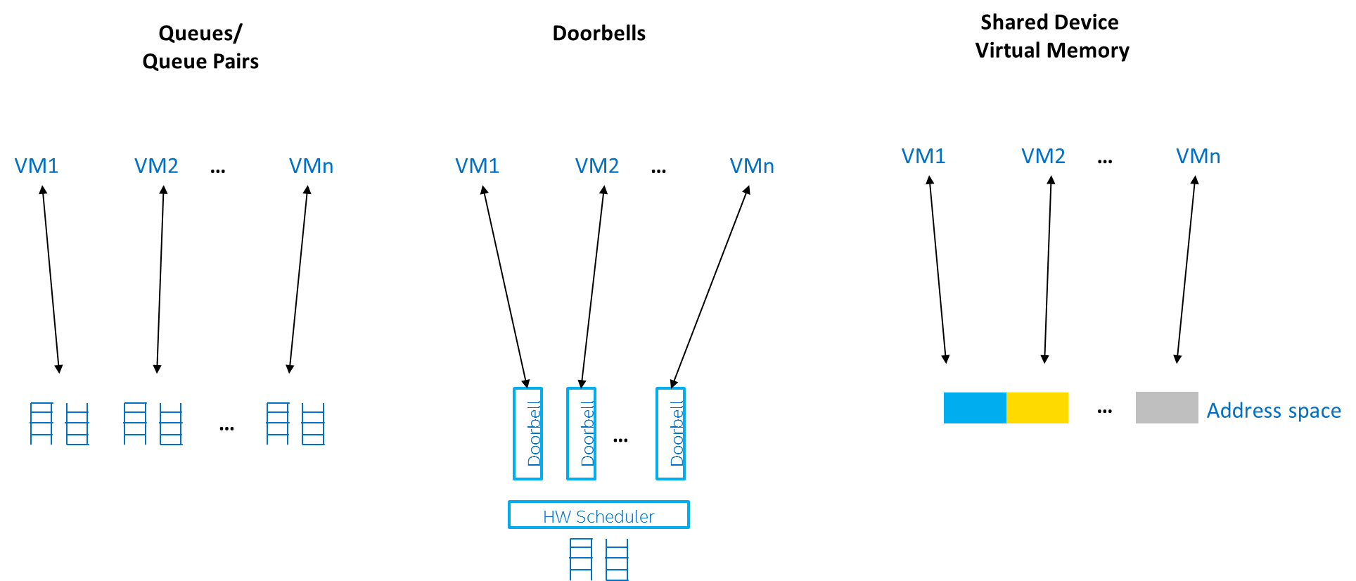
Figure 98 Performance-Critical I/O Resources
The key to implementing mediated pass-through for a specific device is to define the right policy for various I/O resources.
Virtualization Policies for GPU Resources
Figure 99 shows how Intel Processor Graphics works at a high level. Software drivers write commands into a command buffer through the CPU. The Render Engine in the GPU fetches these commands and executes them. The Display Engine fetches pixel data from the Frame Buffer and sends them to the external monitors for display.
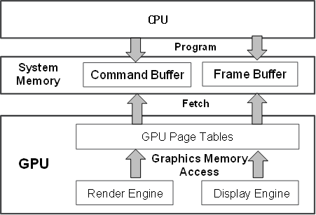
Figure 99 Architecture of Intel Processor Graphics
This architecture abstraction applies to most modern GPUs, but may differ in how graphics memory is implemented. Intel Processor Graphics uses system memory as graphics memory. System memory can be mapped into multiple virtual address spaces by GPU page tables. A 4 GB global virtual address space called “global graphics memory”, accessible from both the GPU and CPU, is mapped through a global page table. Local graphics memory spaces are supported in the form of multiple 4 GB local virtual address spaces, but are only limited to access by the Render Engine through local page tables. Global graphics memory is mostly used for the Frame Buffer and also serves as the Command Buffer. Massive data accesses are made to local graphics memory when hardware acceleration is in progress. Other GPUs have similar page table mechanism accompanying the on-die memory.
The CPU programs the GPU through GPU-specific commands, shown in Figure 99, using a producer-consumer model. The graphics driver programs GPU commands into the Command Buffer, including primary buffer and batch buffer, according to the high-level programming APIs, such as OpenGL* or DirectX*. Then, the GPU fetches and executes the commands. The primary buffer (called a ring buffer) may chain other batch buffers together. The primary buffer and ring buffer are used interchangeably thereafter. The batch buffer is used to convey the majority of the commands (up to ~98% of them) per programming model. A register tuple (head, tail) is used to control the ring buffer. The CPU submits the commands to the GPU by updating the tail, while the GPU fetches commands from the head, and then notifies the CPU by updating the head, after the commands have finished execution. Therefore, when the GPU has executed all commands from the ring buffer, the head and tail pointers are the same.
Having introduced the GPU architecture abstraction, it is important for us to understand how real-world graphics applications use the GPU hardware so that we can virtualize it in VMs efficiently. To do so, we characterized, for some representative GPU-intensive 3D workloads (the Phoronix Test Suite), the usages of the four critical interfaces:
- the Frame Buffer,
- the Command Buffer,
- the GPU Page Table Entries (PTEs), which carry the GPU page tables, and
- the I/O registers, including Memory-Mapped I/O (MMIO) registers, Port I/O (PIO) registers, and PCI configuration space registers for internal state.
Figure 100 shows the average access frequency of running Phoronix 3D workloads on the four interfaces.
The Frame Buffer and Command Buffer exhibit the most performance-critical resources, as shown in Figure 100. When the applications are being loaded, lots of source vertices and pixels are written by the CPU, so the Frame Buffer accesses occur in the range of hundreds of thousands per second. Then at run-time, the CPU programs the GPU through the commands, to render the Frame Buffer, so the Command Buffer accesses become the largest group, also in the hundreds of thousands per second. PTE and I/O accesses are minor in both load and run-time phases ranging in tens of thousands per second.
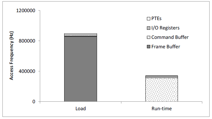
Figure 100 Access Patterns of Running 3D Workloads
High Level Architecture
Figure 101 shows the overall architecture of GVT-g, based on the ACRN hypervisor, with SOS as the privileged VM, and multiple user guests. A GVT-g device model working with the ACRN hypervisor, implements the policies of trap and pass-through. Each guest runs the native graphics driver and can directly access performance-critical resources: the Frame Buffer and Command Buffer, with resource partitioning (as presented later). To protect privileged resources, that is, the I/O registers and PTEs, corresponding accesses from the graphics driver in user VMs are trapped and forwarded to the GVT device model in SOS for emulation. The device model leverages i915 interfaces to access the physical GPU.
In addition, the device model implements a GPU scheduler that runs concurrently with the CPU scheduler in ACRN to share the physical GPU timeslot among the VMs. GVT-g uses the physical GPU to directly execute all the commands submitted from a VM, so it avoids the complexity of emulating the Render Engine, which is the most complex part of the GPU. In the meantime, the resource pass-through of both the Frame Buffer and Command Buffer minimizes the hypervisor’s intervention of CPU accesses, while the GPU scheduler guarantees every VM a quantum time-slice for direct GPU execution. With that, GVT-g can achieve near-native performance for a VM workload.
In Figure 101, the yellow GVT device model works as a client on top of an i915 driver in the SOS. It has a generic Mediated Pass-Through (MPT) interface, compatible with all types of hypervisors. For ACRN, some extra development work is needed for such MPT interfaces. For example, we need some changes in ACRN-DM to make ACRN compatible with the MPT framework. The vGPU lifecycle is the same as the lifecycle of the guest VM creation through ACRN-DM. They interact through sysfs, exposed by the GVT device model.
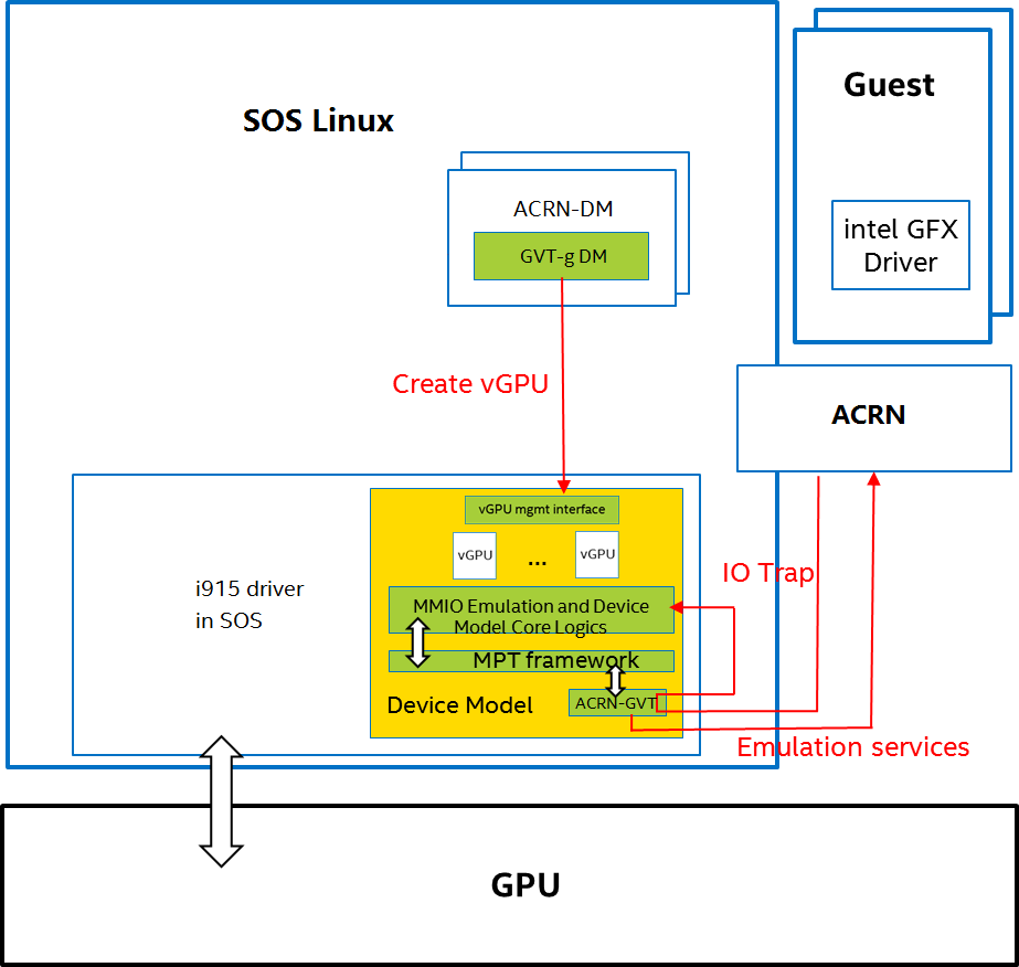
Figure 101 AcrnGT High-level Architecture
Key Techniques
vGPU Device Model
The vGPU Device model is the main component because it constructs the vGPU instance for each guest to satisfy every GPU request from the guest and gives the corresponding result back to the guest.
The vGPU Device Model provides the basic framework to do trap-and-emulation, including MMIO virtualization, interrupt virtualization, and display virtualization. It also handles and processes all the requests internally, such as, command scan and shadow, schedules them in the proper manner, and finally submits to the SOS i915 driver.

Figure 102 GVT-g Device Model
MMIO Virtualization
Intel Processor Graphics implements two PCI MMIO BARs:
- GTTMMADR BAR: Combines both GGTT modification range and Memory Mapped IO range. It is 16 MB on BDW, with 2 MB used by MMIO, 6 MB reserved and 8 MB allocated to GGTT. GGTT starts from GTTMMADR + 8 MB. In this section, we focus on virtualization of the MMIO range, discussing GGTT virtualization later.
- GMADR BAR: As the PCI aperture is used by the CPU to access tiled graphics memory, GVT-g partitions this aperture range among VMs for performance reasons.
A 2 MB virtual MMIO structure is allocated per vGPU instance.
All the virtual MMIO registers are emulated as simple in-memory read-write, that is, guest driver will read back the same value that was programmed earlier. A common emulation handler (for example, intel_gvt_emulate_read/write) is enough to handle such general emulation requirements. However, some registers need to be emulated with specific logic, for example, affected by change of other states or additional audit or translation when updating the virtual register. Therefore, a specific emulation handler must be installed for those special registers.
The graphics driver may have assumptions about the initial device state, which stays with the point when the BIOS transitions to the OS. To meet the driver expectation, we need to provide an initial state of vGPU that a driver may observe on a pGPU. So the host graphics driver is expected to generate a snapshot of physical GPU state, which it does before guest driver’s initialization. This snapshot is used as the initial vGPU state by the device model.
PCI Configuration Space Virtualization
PCI configuration space also needs to be virtualized in the device model. Different implementations may choose to implement the logic within the vGPU device model or in default system device model (for example, ACRN-DM). GVT-g emulates the logic in the device model.
Some information is vital for the vGPU device model, including: Guest PCI BAR, Guest PCI MSI, and Base of ACPI OpRegion.
Legacy VGA Port I/O Virtualization
Legacy VGA is not supported in the vGPU device model. We rely on the default device model (for example, QEMU) to provide legacy VGA emulation, which means either ISA VGA emulation or PCI VGA emulation.
Interrupt Virtualization
The GVT device model does not touch the hardware interrupt in the new architecture, since it is hard to combine the interrupt controlling logic between the virtual device model and the host driver. To prevent architectural changes in the host driver, the host GPU interrupt does not go to the virtual device model and the virtual device model has to handle the GPU interrupt virtualization by itself. Virtual GPU interrupts are categorized into three types:
- Periodic GPU interrupts are emulated by timers. However, a notable exception to this is the VBlank interrupt. Due to the demands of user space compositors, such as Wayland, which requires a flip done event to be synchronized with a VBlank, this interrupt is forwarded from SOS to UOS when SOS receives it from the hardware.
- Event-based GPU interrupts are emulated by the emulation logic. For example, AUX Channel Interrupt.
- GPU command interrupts are emulated by a command parser and workload dispatcher. The command parser marks out which GPU command interrupts are generated during the command execution and the workload dispatcher injects those interrupts into the VM after the workload is finished.
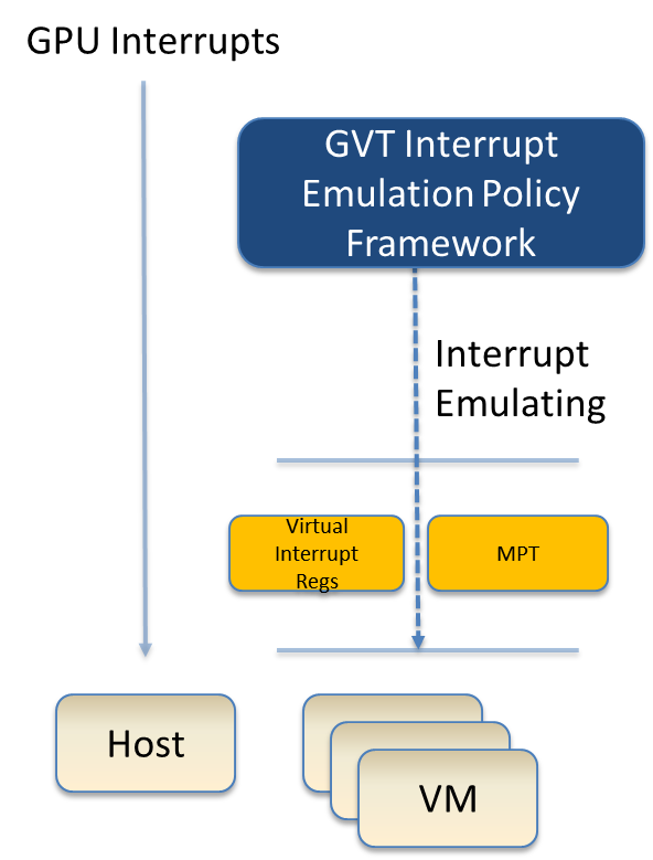
Figure 103 Interrupt Virtualization
Workload Scheduler
The scheduling policy and workload scheduler are decoupled for scalability reasons. For example, a future QoS enhancement will only impact the scheduling policy, any i915 interface change or HW submission interface change (from execlist to GuC) will only need workload scheduler updates.
The scheduling policy framework is the core of the vGPU workload scheduling system. It controls all of the scheduling actions and provides the developer with a generic framework for easy development of scheduling policies. The scheduling policy framework controls the work scheduling process without caring about how the workload is dispatched or completed. All the detailed workload dispatching is hidden in the workload scheduler, which is the actual executer of a vGPU workload.
The workload scheduler handles everything about one vGPU workload. Each hardware ring is backed by one workload scheduler kernel thread. The workload scheduler picks the workload from current vGPU workload queue and communicates with the virtual HW submission interface to emulate the “schedule-in” status for the vGPU. It performs context shadow, Command Buffer scan and shadow, PPGTT page table pin/unpin/out-of-sync, before submitting this workload to the host i915 driver. When the vGPU workload is completed, the workload scheduler asks the virtual HW submission interface to emulate the “schedule-out” status for the vGPU. The VM graphics driver then knows that a GPU workload is finished.
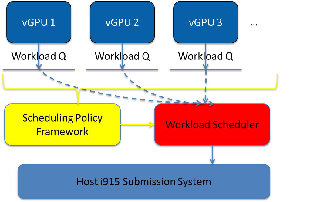
Figure 104 GVT-g Scheduling Framework
Workload Submission Path
Software submits the workload using the legacy ring buffer mode on Intel
Processor Graphics before Broadwell, which is no longer supported by the
GVT-g virtual device model. A new HW submission interface named
“Execlist” is introduced since Broadwell. With the new HW submission
interface, software can achieve better programmability and easier
context management. In Intel GVT-g, the vGPU submits the workload
through the virtual HW submission interface. Each workload in submission
will be represented as an intel_vgpu_workload data structure, a vGPU
workload, which will be put on a per-vGPU and per-engine workload queue
later after performing a few basic checks and verifications.
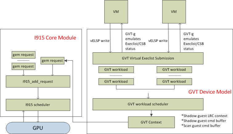
Figure 105 GVT-g Workload Submission
Display Virtualization
GVT-g reuses the i915 graphics driver in the SOS to initialize the Display Engine, and then manages the Display Engine to show different VM frame buffers. When two vGPUs have the same resolution, only the frame buffer locations are switched.
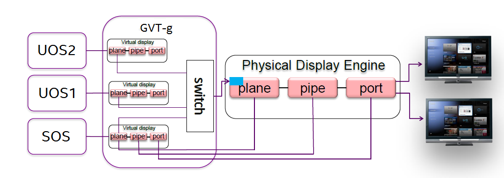
Figure 106 Display Virtualization
Direct Display Model
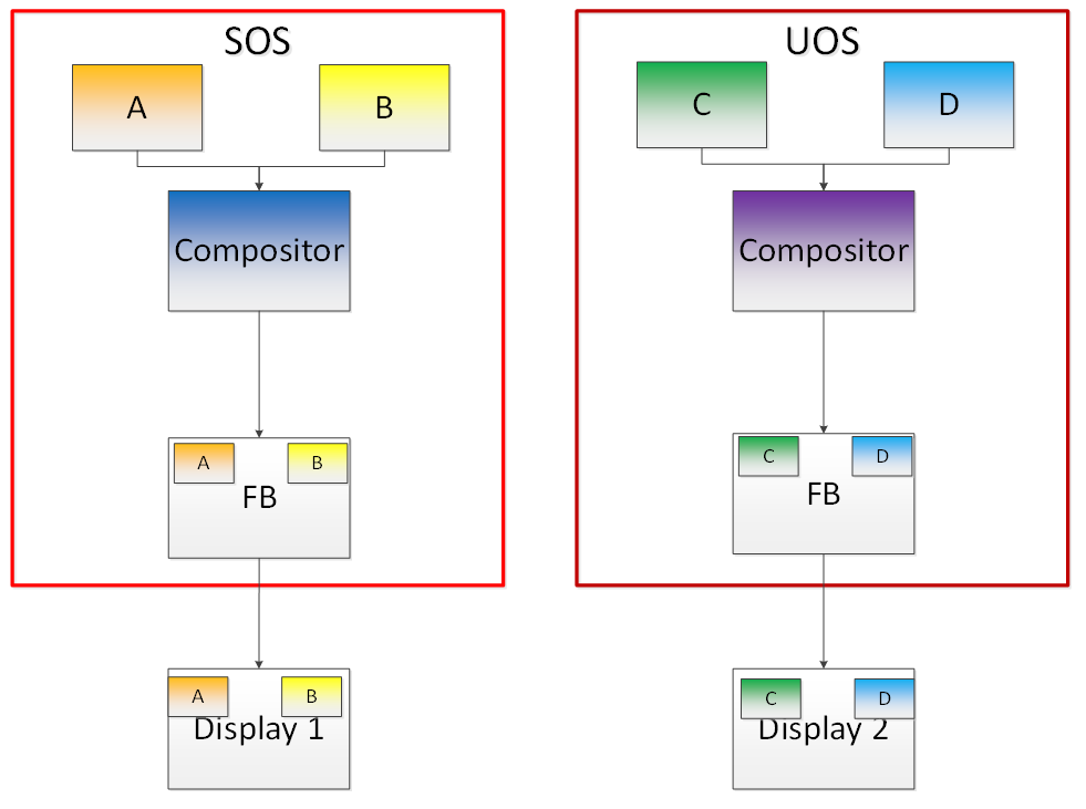
Figure 107 Direct Display Model
A typical automotive use case is where there are two displays in the car and each one needs to show one domain’s content, with the two domains being the Instrument cluster and the In Vehicle Infotainment (IVI). As shown in Figure 107, this can be accomplished through the direct display model of GVT-g, where the SOS and UOS are each assigned all HW planes of two different pipes. GVT-g has a concept of display owner on a per HW plane basis. If it determines that a particular domain is the owner of a HW plane, then it allows the domain’s MMIO register write to flip a frame buffer to that plane to go through to the HW. Otherwise, such writes are blocked by the GVT-g.
Indirect Display Model
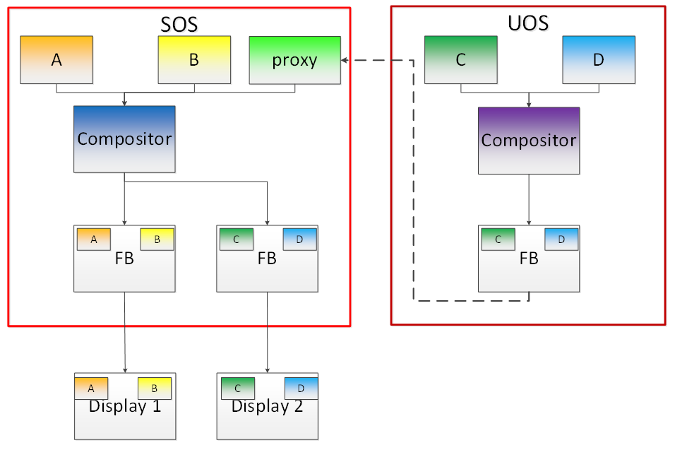
Figure 108 Indirect Display Model
For security or fastboot reasons, it may be determined that the UOS is either not allowed to display its content directly on the HW or it may be too late before it boots up and displays its content. In such a scenario, the responsibility of displaying content on all displays lies with the SOS. One of the use cases that can be realized is to display the entire frame buffer of the UOS on a secondary display. GVT-g allows for this model by first trapping all MMIO writes by the UOS to the HW. A proxy application can then capture the address in GGTT where the UOS has written its frame buffer and using the help of the Hypervisor and the SOS’s i915 driver, can convert the Guest Physical Addresses (GPAs) into Host Physical Addresses (HPAs) before making a texture source or EGL image out of the frame buffer and then either post processing it further or simply displaying it on a HW plane of the secondary display.
GGTT-Based Surface Sharing
One of the major automotive use case is called “surface sharing”. This use case requires that the SOS accesses an individual surface or a set of surfaces from the UOS without having to access the entire frame buffer of the UOS. Unlike the previous two models, where the UOS did not have to do anything to show its content and therefore a completely unmodified UOS could continue to run, this model requires changes to the UOS.
This model can be considered an extension of the indirect display model. Under the indirect display model, the UOS’s frame buffer was temporarily pinned by it in the video memory access through the Global graphics translation table. This GGTT-based surface sharing model takes this a step further by having a compositor of the UOS to temporarily pin all application buffers into GGTT. It then also requires the compositor to create a metadata table with relevant surface information such as width, height, and GGTT offset, and flip that in lieu of the frame buffer. In the SOS, the proxy application knows that the GGTT offset has been flipped, maps it, and through it can access the GGTT offset of an application that it wants to access. It is worth mentioning that in this model, UOS applications did not require any changes, and only the compositor, Mesa, and i915 driver had to be modified.
This model has a major benefit and a major limitation. The benefit is that since it builds on top of the indirect display model, there are no special drivers necessary for it on either SOS or UOS. Therefore, any Real Time Operating System (RTOS) that use this model can simply do so without having to implement a driver, the infrastructure for which may not be present in their operating system. The limitation of this model is that video memory dedicated for a UOS is generally limited to a couple of hundred MBs. This can easily be exhausted by a few application buffers so the number and size of buffers is limited. Since it is not a highly-scalable model, in general, Intel recommends the Hyper DMA buffer sharing model, described next.
Hyper DMA Buffer Sharing
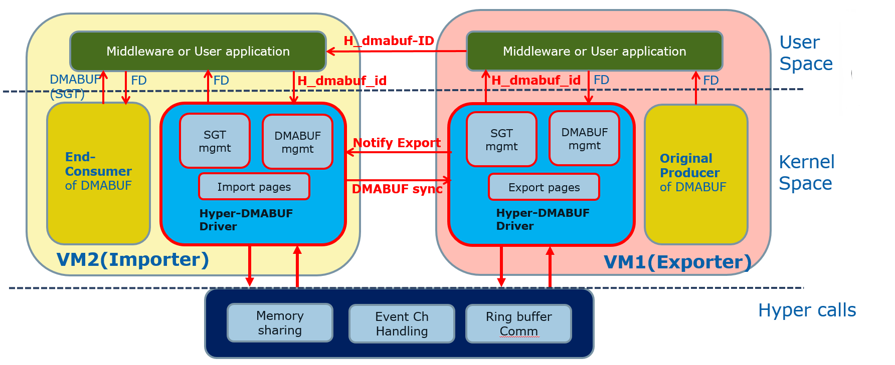
Figure 109 Hyper DMA Buffer Design
Another approach to surface sharing is Hyper DMA Buffer sharing. This model extends the Linux DMA buffer sharing mechanism where one driver is able to share its pages with another driver within one domain.
Applications buffers are backed by i915 Graphics Execution Manager Buffer Objects (GEM BOs). As in GGTT surface sharing, this model also requires compositor changes. The compositor of UOS requests i915 to export these application GEM BOs and then passes them on to a special driver called the Hyper DMA Buf exporter whose job is to create a scatter gather list of pages mapped by PDEs and PTEs and export a Hyper DMA Buf ID back to the compositor.
The compositor then shares this Hyper DMA Buf ID with the SOS’s Hyper DMA Buf importer driver which then maps the memory represented by this ID in the SOS. A proxy application in the SOS can then provide the ID of this driver to the SOS i915, which can create its own GEM BO. Finally, the application can use it as an EGL image and do any post processing required before either providing it to the SOS compositor or directly flipping it on a HW plane in the compositor’s absence.
This model is highly scalable and can be used to share up to 4 GB worth of pages. It is also not limited to only sharing graphics buffers. Other buffers for the IPU and others, can also be shared with it. However, it does require that the SOS port the Hyper DMA Buffer importer driver. Also, the SOS OS must comprehend and implement the DMA buffer sharing model.
For detailed information about this model, please refer to the Linux HYPER_DMABUF Driver High Level Design.
Plane-Based Domain Ownership
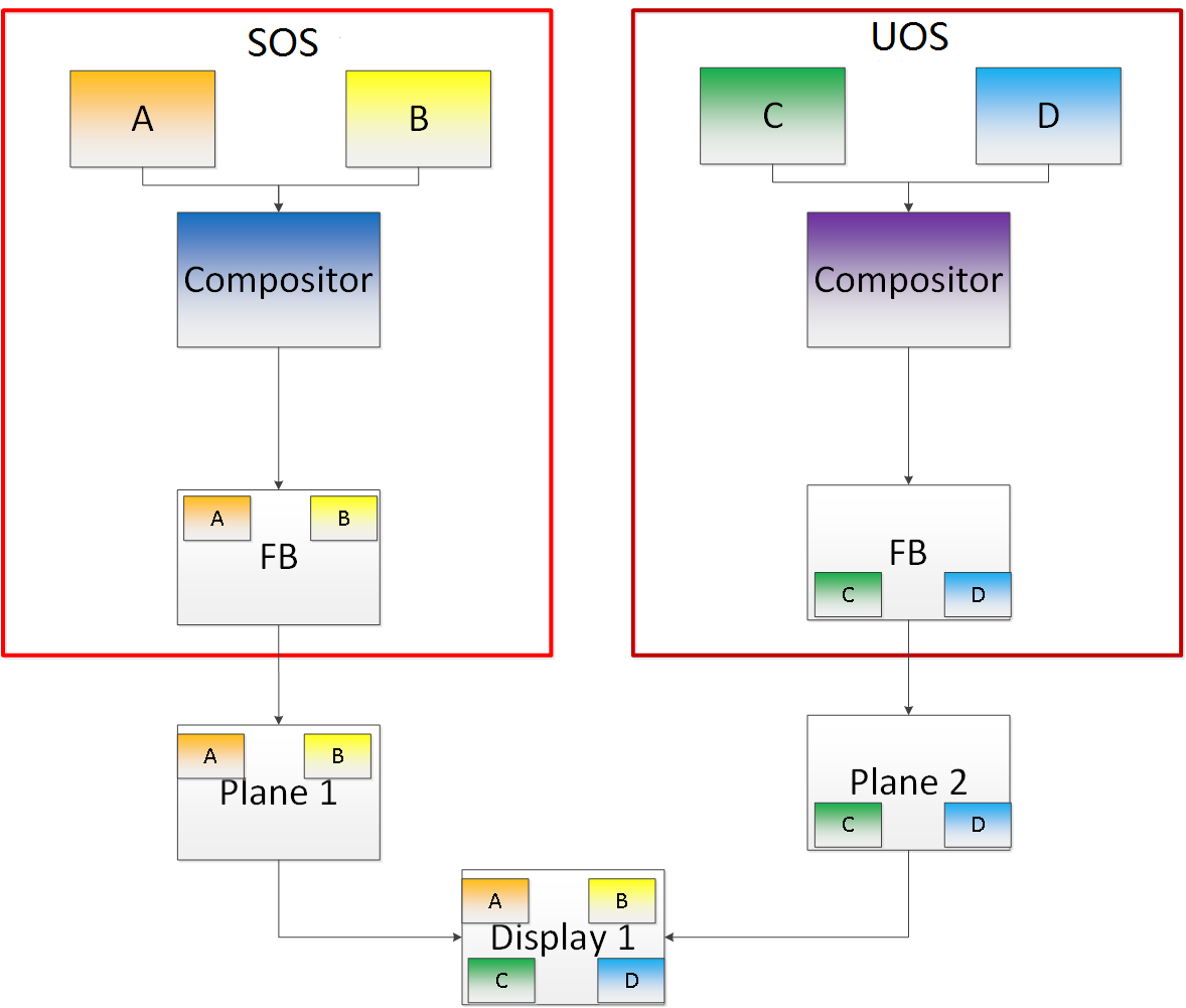
Figure 110 Plane-Based Domain Ownership
Yet another mechanism for showing content of both the SOS and UOS on the same physical display is called plane-based domain ownership. Under this model, both the SOS and UOS are provided a set of HW planes that they can flip their contents on to. Since each domain provides its content, there is no need for any extra composition to be done through the SOS. The display controller handles alpha blending contents of different domains on a single pipe. This saves on any complexity on either the SOS or the UOS SW stack.
It is important to provide only specific planes and have them statically assigned to different Domains. To achieve this, the i915 driver of both domains is provided a command line parameter that specifies the exact planes that this domain has access to. The i915 driver then enumerates only those HW planes and exposes them to its compositor. It is then left to the compositor configuration to use these planes appropriately and show the correct content on them. No other changes are necessary.
While the biggest benefit of this model is that is extremely simple and quick to implement, it also has some drawbacks. First, since each domain is responsible for showing the content on the screen, there is no control of the UOS by the SOS. If the UOS is untrusted, this could potentially cause some unwanted content to be displayed. Also, there is no post processing capability, except that provided by the display controller (for example, scaling, rotation, and so on). So each domain must provide finished buffers with the expectation that alpha blending with another domain will not cause any corruption or unwanted artifacts.
Graphics Memory Virtualization
To achieve near-to-native graphics performance, GVT-g passes through the performance-critical operations, such as Frame Buffer and Command Buffer from the VM. For the global graphics memory space, GVT-g uses graphics memory resource partitioning and an address space ballooning mechanism. For local graphics memory spaces, GVT-g implements per-VM local graphics memory through a render context switch because local graphics memory is only accessible by the GPU.
Global Graphics Memory
Graphics Memory Resource Partitioning
GVT-g partitions the global graphics memory among VMs. Splitting the CPU/GPU scheduling mechanism requires that the global graphics memory of different VMs can be accessed by the CPU and the GPU simultaneously. Consequently, GVT-g must, at any time, present each VM with its own resource, leading to the resource partitioning approaching, for global graphics memory, as shown in Figure 111.
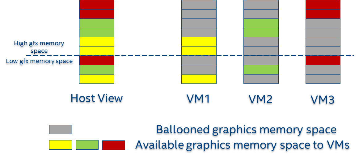
Figure 111 Memory Partition and Ballooning
The performance impact of reduced global graphics memory resource due to memory partitioning is very limited according to various test results.
Address Space Ballooning
The address space ballooning technique is introduced to eliminate the address translation overhead, shown in Figure 111. GVT-g exposes the partitioning information to the VM graphics driver through the PVINFO MMIO window. The graphics driver marks the other VMs’ regions as ‘ballooned’, and reserves them as not being used from its graphics memory allocator. Under this design, the guest view of global graphics memory space is exactly the same as the host view and the driver programmed addresses, using guest physical address, can be directly used by the hardware. Address space ballooning is different from traditional memory ballooning techniques. Memory ballooning is for memory usage control concerning the number of ballooned pages, while address space ballooning is to balloon special memory address ranges.
Another benefit of address space ballooning is that there is no address translation overhead as we use the guest Command Buffer for direct GPU execution.
Per-VM Local Graphics Memory
GVT-g allows each VM to use the full local graphics memory spaces of its own, similar to the virtual address spaces on the CPU. The local graphics memory spaces are only visible to the Render Engine in the GPU. Therefore, any valid local graphics memory address, programmed by a VM, can be used directly by the GPU. The GVT-g device model switches the local graphics memory spaces, between VMs, when switching render ownership.
GPU Page Table Virtualization
Shared Shadow GGTT
To achieve resource partitioning and address space ballooning, GVT-g implements a shared shadow global page table for all VMs. Each VM has its own guest global page table to translate the graphics memory page number to the Guest memory Page Number (GPN). The shadow global page table is then translated from the graphics memory page number to the Host memory Page Number (HPN).
The shared shadow global page table maintains the translations for all VMs to support concurrent accesses from the CPU and GPU concurrently. Therefore, GVT-g implements a single, shared shadow global page table by trapping guest PTE updates, as shown in Figure 112. The global page table, in MMIO space, has 1024K PTE entries, each pointing to a 4 KB system memory page, so the global page table overall creates a 4 GB global graphics memory space. GVT-g audits the guest PTE values according to the address space ballooning information before updating the shadow PTE entries.
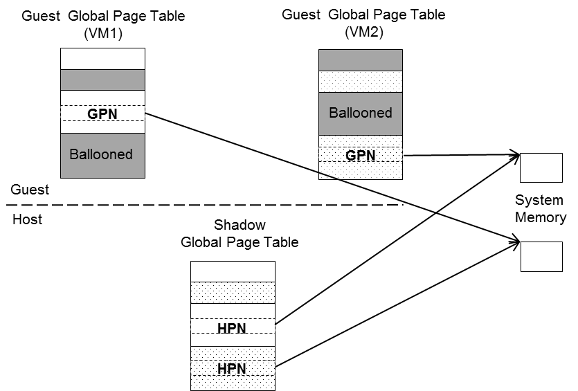
Figure 112 Shared Shadow Global Page Table
Per-VM Shadow PPGTT
To support local graphics memory access pass-through, GVT-g implements per-VM shadow local page tables. The local graphics memory is only accessible from the Render Engine. The local page tables have two-level paging structures, as shown in Figure 113.
The first level, Page Directory Entries (PDEs), located in the global page table, points to the second level, Page Table Entries (PTEs) in system memory, so guest accesses to the PDE are trapped and emulated, through the implementation of shared shadow global page table.
GVT-g also write-protects a list of guest PTE pages for each VM. The GVT-g device model synchronizes the shadow page with the guest page, at the time of write-protection page fault, and switches the shadow local page tables at render context switches.
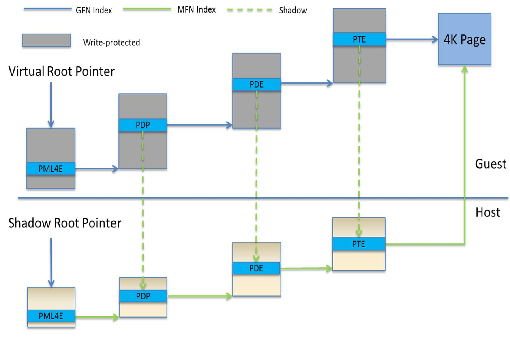
Figure 113 Per-VM Shadow PPGTT
Prioritized Rendering and Preemption
Different Schedulers and Their Roles
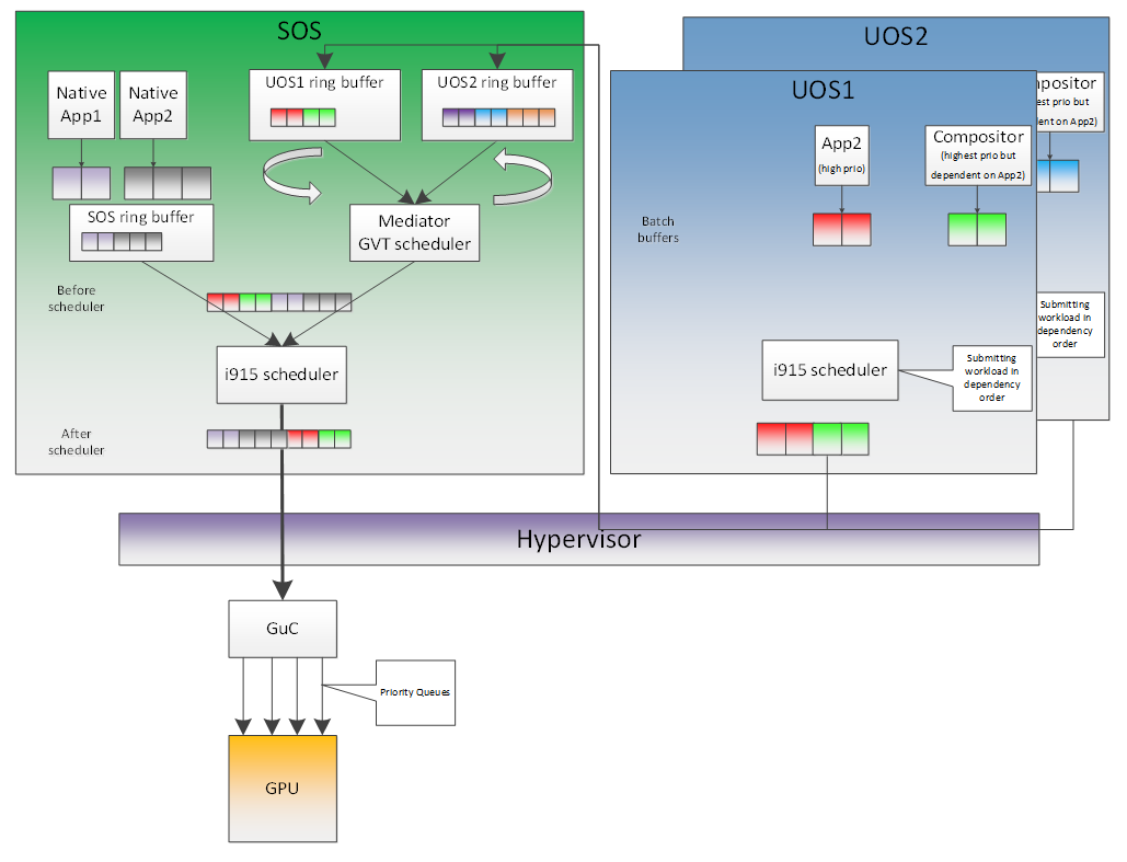
Figure 114 Scheduling Policy
In the system, there are three different schedulers for the GPU:
- i915 UOS scheduler
- Mediator GVT scheduler
- i915 SOS scheduler
Since UOS always uses the host-based command submission (ELSP) model, and it never accesses the GPU or the Graphic Micro Controller (GuC) directly, its scheduler cannot do any preemption by itself. The i915 scheduler does ensure batch buffers are submitted in dependency order, that is, if a compositor had to wait for an application buffer to finish before its workload can be submitted to the GPU, then the i915 scheduler of the UOS ensures that this happens.
The UOS assumes that by submitting its batch buffers to the Execlist Submission Port (ELSP), the GPU will start working on them. However, the MMIO write to the ELSP is captured by the Hypervisor, which forwards these requests to the GVT module. GVT then creates a shadow context based on this batch buffer and submits the shadow context to the SOS i915 driver.
However, it is dependent on a second scheduler called the GVT scheduler. This scheduler is time based and uses a round robin algorithm to provide a specific time for each UOS to submit its workload when it is considered as a “render owner”. The workload of the UOSs that are not render owners during a specific time period end up waiting in the virtual GPU context until the GVT scheduler makes them render owners. The GVT shadow context submits only one workload at a time, and once the workload is finished by the GPU, it copies any context state back to DomU and sends the appropriate interrupts before picking up any other workloads from either this UOS or another one. This also implies that this scheduler does not do any preemption of workloads.
Finally, there is the i915 scheduler in the SOS. This scheduler uses the GuC or ELSP to do command submission of SOS local content as well as any content that GVT is submitting to it on behalf of the UOSs. This scheduler uses GuC or ELSP to preempt workloads. GuC has four different priority queues, but the SOS i915 driver uses only two of them. One of them is considered high priority and the other is normal priority with a GuC rule being that any command submitted on the high priority queue would immediately try to preempt any workload submitted on the normal priority queue. For ELSP submission, the i915 will submit a preempt context to preempt the current running context and then wait for the GPU engine to be idle.
While the identification of workloads to be preempted is decided by customizable scheduling policies, once a candidate for preemption is identified, the i915 scheduler simply submits a preemption request to the GuC high-priority queue. Based on the HW’s ability to preempt (on an Apollo Lake SoC, 3D workload is preemptible on a 3D primitive level with some exceptions), the currently executing workload is saved and preempted. The GuC informs the driver using an interrupt of a preemption event occurring. After handling the interrupt, the driver submits the high-priority workload through the normal priority GuC queue. As such, the normal priority GuC queue is used for actual execbuf submission most of the time with the high-priority GuC queue only being used for the preemption of lower-priority workload.
Scheduling policies are customizable and left to customers to change if they are not satisfied with the built-in i915 driver policy, where all workloads of the SOS are considered higher priority than those of the UOS. This policy can be enforced through an SOS i915 kernel command line parameter, and can replace the default in-order command submission (no preemption) policy.
AcrnGT
ACRN is a flexible, lightweight reference hypervisor, built with real-time and safety-criticality in mind, optimized to streamline embedded development through an open source platform.
AcrnGT is the GVT-g implementation on the ACRN hypervisor. It adapts the MPT interface of GVT-g onto ACRN by using the kernel APIs provided by ACRN.
Figure 115 shows the full architecture of AcrnGT with a Linux Guest OS and an Android Guest OS.

Figure 115 Full picture of the AcrnGT
AcrnGT in kernel
The AcrnGT module in the SOS kernel acts as an adaption layer to connect between GVT-g in the i915, the VHM module, and the ACRN-DM user space application:
- AcrnGT module implements the MPT interface of GVT-g to provide services to it, including set and unset trap areas, set and unset write-protection pages, etc.
- It calls the VHM APIs provided by the ACRN VHM module in the SOS kernel, to eventually call into the routines provided by ACRN hypervisor through hyper-calls.
- It provides user space interfaces through
sysfsto the user space ACRN-DM, so that DM can manage the lifecycle of the virtual GPUs.
AcrnGT in DM
To emulate a PCI device to a Guest, we need an AcrnGT sub-module in the ACRN-DM. This sub-module is responsible for:
- registering the virtual GPU device to the PCI device tree presented to guest;
- registerng the MMIO resources to ACRN-DM so that it can reserve resources in ACPI table;
- managing the lifecycle of the virtual GPU device, such as creation, destruction, and resetting according to the state of the virtual machine.