Device Passthrough
A critical part of virtualization is virtualizing devices: exposing all aspects of a device including its I/O, interrupts, DMA, and configuration. There are three typical device virtualization methods: emulation, para-virtualization, and passthrough. All emulation, para-virtualization and passthrough are used in ACRN project. Device emulation is discussed in I/O Emulation High-Level Design, para-virtualization is discussed in Virtio Devices High-Level Design and device passthrough will be discussed here.
In the ACRN project, device emulation means emulating all existing hardware resources through the Device Model, a software component running in the Service VM. Device emulation must maintain the same SW interface as a native device, providing transparency to the VM software stack. Passthrough implemented in the hypervisor assigns a physical device to a VM so the VM can access the hardware device directly with minimal (if any) VMM involvement.
The difference between device emulation and passthrough is shown in Figure 139. You can notice device emulation has a longer access path which causes worse performance compared with passthrough. Passthrough can deliver near-native performance, but can’t support device sharing.
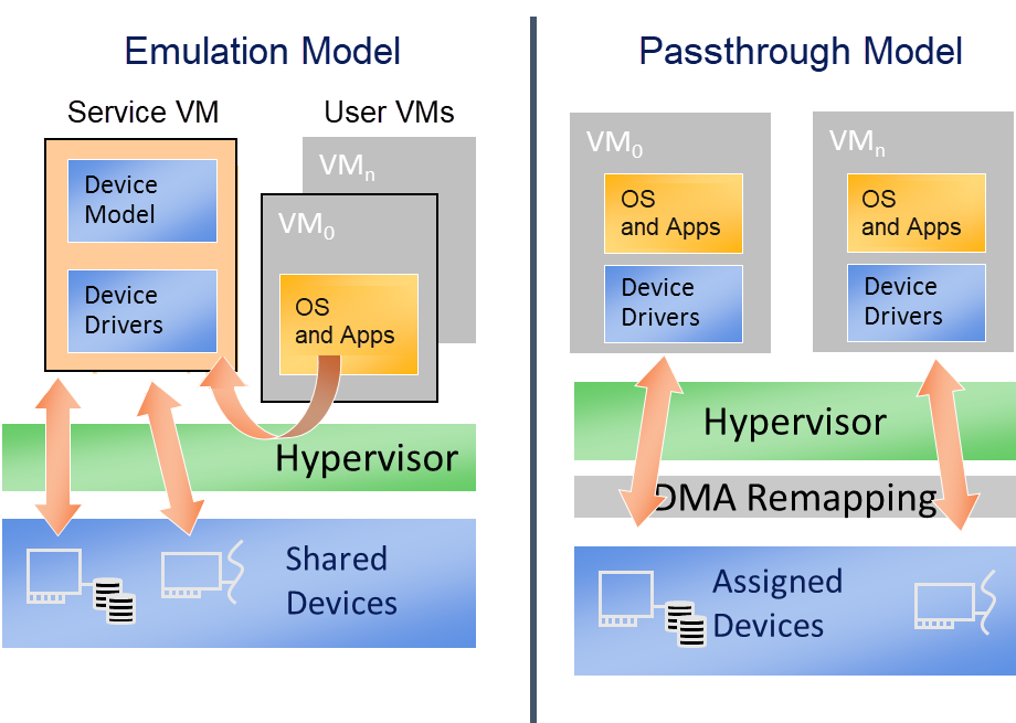
Figure 139 Difference Between Emulation and Passthrough
Passthrough in the hypervisor provides the following functionalities to allow the VM to access PCI devices directly:
VT-d DMA remapping for PCI devices: hypervisor will set up DMA remapping during VM initialization phase.
VT-d interrupt-remapping for PCI devices: hypervisor will enable VT-d interrupt-remapping for PCI devices for security considerations.
MMIO remapping between virtual and physical BAR
Device configuration emulation
Remapping interrupts for PCI devices
ACPI configuration virtualization
GSI sharing violation check
The following diagram details the passthrough initialization control flow in ACRN for a post-launched VM:
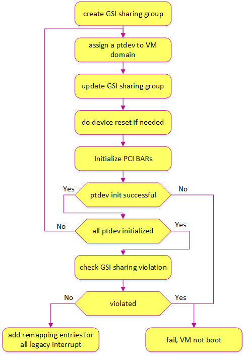
Figure 140 Passthrough Devices Initialization Control Flow
Passthrough Device Status
Most common devices on supported platforms are enabled for passthrough, as detailed here:
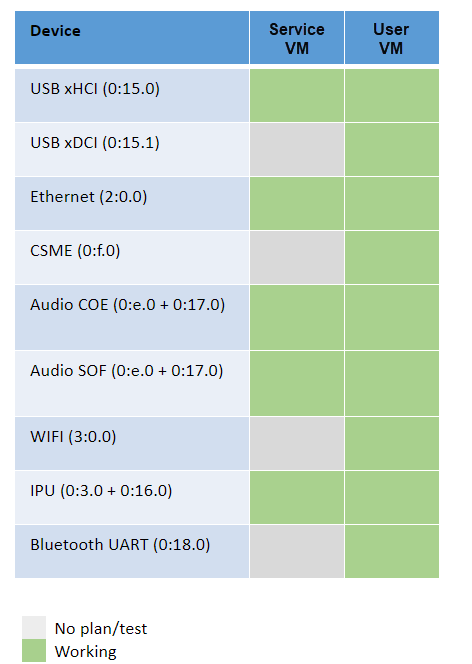
Figure 141 Passthrough Device Status
Owner of Passthrough Devices
ACRN hypervisor will do PCI enumeration to discover the PCI devices on the platform. According to the hypervisor/VM configurations, the owner of these PCI devices can be one of the following 4 cases:
Hypervisor: Hypervisor uses a UART device as the console in debug version for debugging purposes, so the UART device is owned by the hypervisor and is not visible to any VM. For now, UART is the only PCI device that can be owned by the hypervisor.
Pre-launched VM: The passthrough devices that will be used in a pre-launched VM are predefined in the VM configuration. These passthrough devices are owned by the pre-launched VM after the VM is created. These devices will not be removed from the pre-launched VM. There can be pre-launched VMs in partitioned mode and hybrid mode.
Service VM: All the passthrough devices except those described above (owned by hypervisor or pre-launched VMs) are assigned to the Service VM. And some of these devices can be assigned to a post-launched VM according to the passthrough device list specified in the parameters of the ACRN Device Model.
Post-launched VM: A list of passthrough devices can be specified in the parameters of the ACRN Device Model. When creating a post-launched VM, these specified devices will be moved from the Service VM domain to the post-launched VM domain. After the post-launched VM is powered-off, these devices will be moved back to the Service VM domain.
VT-d DMA Remapping
To enable passthrough, for VM DMA access the VM can only support GPA, while a physical DMA requires HPA. One work-around is building identity mapping so that GPA is equal to HPA, but this is not recommended as some VMs don’t support relocation well. To address this issue, Intel introduces VT-d in the chipset to add one remapping engine to translate GPA to HPA for DMA operations.
Each VT-d engine (DMAR Unit) maintains a remapping structure similar to a page table with device BDF (Bus/Dev/Func) as input and final page table for GPA/HPA translation as output. The GPA/HPA translation page table is similar to a normal multi-level page table.
VM DMA depends on Intel VT-d to do the translation from GPA to HPA, so we need to enable VT-d IOMMU engine in ACRN before we can passthrough any device. The Service VM in ACRN is a VM running in non-root mode which also depends on VT-d to access a device. In Service VM DMA remapping engine settings, GPA is equal to HPA.
ACRN hypervisor checks DMA-Remapping Hardware unit Definition (DRHD) in the host DMAR ACPI table to get basic information, then sets up each DMAR unit. For simplicity, ACRN reuses the EPT table as the translation table in the DMAR unit for each passthrough device. The control flow of assigning and deassigning a passthrough device to/from a post-launched VM is shown in the following figures:
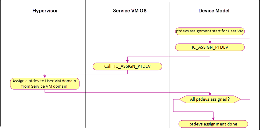
Figure 142 Ptdev Assignment Control Flow
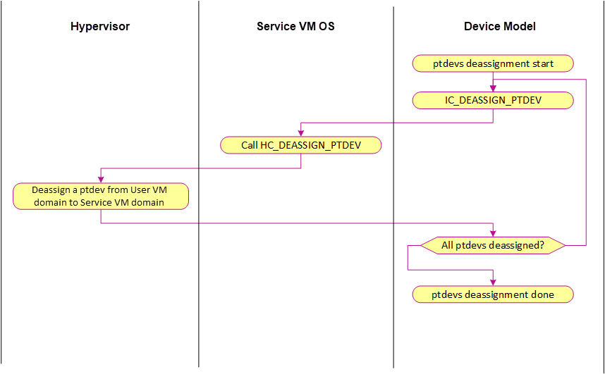
Figure 143 Ptdev Deassignment Control Flow
VT-d Interrupt-Remapping
The VT-d interrupt-remapping architecture enables system software to control and censor external interrupt requests generated by all sources including those from interrupt controllers (I/OxAPICs), MSI/MSI-X capable devices including endpoints, root-ports and Root-Complex integrated end-points. ACRN requires enabling the VT-d interrupt-remapping feature for security reasons. If the VT-d hardware doesn’t support interrupt-remapping, then ACRN will refuse to boot VMs. VT-d interrupt-remapping is NOT related to the translation from physical interrupt to virtual interrupt or vice versa. The term VT-d interrupt-remapping remaps the interrupt index in the VT-d interrupt-remapping table to the physical interrupt vector after checking the external interrupt request is valid. The hypervisor still needs to translate the physical vector to the virtual vector, which is also described in the below section Interrupt Remapping.
VT-d posted interrupt (PI) enables direct delivery of external interrupts from passthrough devices to VMs without having to exit to the hypervisor, thereby improving interrupt performance. ACRN uses VT-d posted interrupts if the platform supports them. VT-d distinguishes between remapped and posted interrupt modes by bit 15 in the low 64-bit of the interrupt-remapping table entry. If cleared, the entry is remapped. If set, it’s posted. The idea is to keep a Posted Interrupt Descriptor (PID) in memory. The PID is a 64-byte data structure that contains several fields:
- Posted Interrupt Request (PIR):
a 256-bit field, one bit per request vector; this is where the interrupts are posted.
- Suppress Notification (SN):
determines whether to notify (
SN=0) or not notify (SN=1) the CPU for non-urgent interrupts. For ACRN, all interrupts are treated as non-urgent. ACRN sets SN=0 during initialization and then never changes it at runtime.- Notification Vector (NV):
the CPU must be notified with an interrupt and this field specifies the vector for notification.
- Notification Destination (NDST):
the physical APIC-ID of the destination. ACRN does not support vCPU migration. One vCPU always runs on the same pCPU, so for ACRN, NDST is never changed after initialization.
- Outstanding Notification (ON):
indicates if a notification event is outstanding
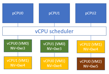
The ACRN scheduler supports vCPU scheduling, where two or more vCPUs can share the same pCPU using a time sharing technique. One issue emerges here for the VT-d posted interrupt handling process, where IRQs could happen when the target vCPU is in a halted state. We need to handle the case where the running vCPU disrupted by the external interrupt, is not the target vCPU that should have received the external interrupt.
Consider this scenario:
vCPU0 runs on pCPU0 and then enters a halted state,
ACRN scheduler now chooses vCPU1 to run on pCPU0.
If an external interrupt from an assigned device destined to vCPU0 happens at this time, we do not want this interrupt to be incorrectly consumed by vCPU1 running on pCPU0. This would happen if we allocate the same Activation Notification Vector (ANV) to all vCPUs.
To circumvent this issue, ACRN allocates unique ANVs for each vCPU that belongs to the same pCPU. The ANVs need only be unique within each pCPU, not across all vCPUs. Since vCPU0’s ANV is different from vCPU1’s ANV, if vCPU0 is in a halted state, external interrupts from an assigned device destined to vCPU0 delivered through the PID will not trigger the posted interrupt processing. Instead, a VMExit to ACRN happens that can then process the event such as waking up the halted vCPU0 and kick it to run on pCPU0.
For ACRN, CONFIG_MAX_VM_NUM vCPUs may be running on top of a pCPU. ACRN
does not support two vCPUs of the same VM running on top of the same
pCPU. This reduces the number of pre-allocated ANVs for posted
interrupts to CONFIG_MAX_VM_NUM, and enables ACRN to avoid switching
between active and wake-up vector values in the posted interrupt
descriptor on vCPU scheduling state changes. ACRN uses the following
formula to assign posted interrupt vectors to vCPUs:
NV = POSTED_INTR_VECTOR + vcpu->vm->vm_id
where POSTED_INTR_VECTOR is the starting vector (0xe3) for posted interrupts.
ACRN maintains a per-PCPU vCPU array that stores the pointers to
assigned vCPUs for each pCPU and is indexed by vcpu->vm->vm_id.
When the vCPU is created, ACRN adds the vCPU to the containing pCPU’s
vCPU array. When the vCPU is offline, ACRN removes the vCPU from the
related vCPU array.
An example to illustrate our solution:
ACRN sets SN=0 during initialization and then never changes it at
runtime. This means posted interrupt notification is never suppressed.
After posting the interrupt in Posted Interrupt Request (PIR), VT-d will
always notify the CPU using the interrupt vector NV, in both root and
non-root mode. With this scheme, if the target vCPU is running under
VMX non-root mode, it will receive the interrupts coming from the
passthrough device without a VMExit (and therefore without any
intervention of the ACRN hypervisor).
If the target vCPU is in a halted state (under VMX non-root mode), a scheduling request will be raised to wake it up. This is needed to achieve real time behavior. If an RT-VM is waiting for an event, when the event is fired (a PI interrupt fires), we need to wake up the VM immediately.
MMIO Remapping
For PCI MMIO BAR, the hypervisor builds EPT mapping between the virtual BAR and physical BAR, then the VM can access MMIO directly. There is one exception: an MSI-X table is also in an MMIO BAR. The hypervisor needs to trap the accesses to the MSI-X table. So the pages that have an MSI-X table should not be accessed by the VM directly. EPT mapping is not built for pages that have an MSI-X table.
Device Configuration Emulation
The PCI configuration space can be accessed by a PCI-compatible Configuration Mechanism (IO port 0xCF8/CFC) and the PCI Express Enhanced Configuration Access Mechanism (PCI MMCONFIG). The ACRN hypervisor traps this PCI configuration space access and emulates it. Refer to Split Device Model for details.
MSI-X Table Emulation
VM accesses to an MSI-X table should be trapped so that the hypervisor has the information to map the virtual vector and physical vector. EPT mapping should be skipped for the 4KB pages that have an MSI-X table.
There are three situations for the emulation of MSI-X tables:
Service VM: Accesses to an MSI-X table are handled by the hypervisor MMIO handler (4KB adjusted up and down). The hypervisor remaps the interrupts.
Post-launched VM: Accesses to an MSI-X table are handled by the Device Model MMIO handler (4KB adjusted up and down). When the Device Model (Service VM) writes to the table, it will be intercepted by the hypervisor MMIO handler. The hypervisor remaps the interrupts.
Pre-launched VM: Writes to the MMIO region in an MSI-X table BAR are handled by the hypervisor MMIO handler. If the offset falls within the MSI-X table (offset, offset+tables_size), the hypervisor remaps the interrupts.
Interrupt Remapping
When the physical interrupt of a passthrough device happens, the hypervisor has
to distribute it to the relevant VM according to interrupt remapping
relationships. The structure ptirq_remapping_info is used to define
the subordination relation between physical interrupt and VM, the
virtual destination, etc. See the following figure for details:
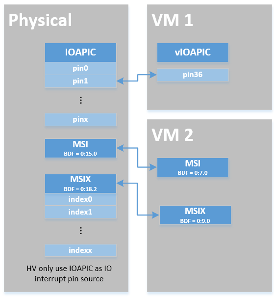
Figure 144 Remapping of Physical Interrupts
There are two different types of interrupt sources: IOAPIC and MSI. The hypervisor will record different information for interrupt distribution: physical and virtual IOAPIC pin for IOAPIC source, physical and virtual BDF and other information for MSI source.
Service VM passthrough is also in the scope of interrupt remapping which is done on-demand rather than on hypervisor initialization.
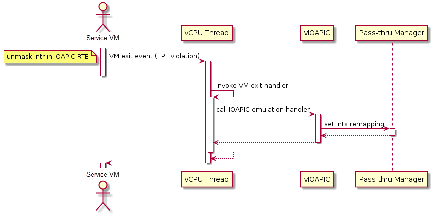
Figure 145 Initialization of Remapping of Virtual IOAPIC Interrupts for Service VM
Figure 145 above illustrates how remapping of (virtual) IOAPIC interrupts are remapped for the Service VM. VM exit occurs whenever the Service VM tries to unmask an interrupt in (virtual) IOAPIC by writing to the Redirection Table Entry (or RTE). The hypervisor then invokes the IOAPIC emulation handler (refer to I/O Emulation High-Level Design for details on I/O emulation) which calls APIs to set up a remapping for the to-be-unmasked interrupt.
Remapping of (virtual) MSI interrupts are set up in a similar sequence:
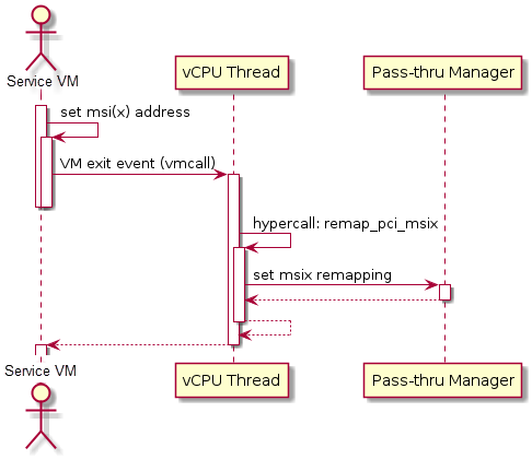
Figure 146 Initialization of Remapping of Virtual MSI for Service VM
This figure illustrates how mappings of MSI or MSI-X are set up for the Service VM. The Service VM is responsible for issuing a hypercall to notify the hypervisor before it configures the PCI configuration space to enable an MSI. The hypervisor takes this opportunity to set up a remapping for the given MSI or MSI-X before it is actually enabled by the Service VM.
When the User VM needs to access the physical device by passthrough, it uses the following steps:
User VM gets a virtual interrupt.
VM exit happens and the trapped vCPU is the target where the interrupt will be injected.
Hypervisor handles the interrupt and translates the vector according to
ptirq_remapping_info.Hypervisor delivers the interrupt to the User VM.
When the Service VM needs to use the physical device, the passthrough is also active because the Service VM is the first VM. The detail steps are:
Service VM gets all physical interrupts. It assigns different interrupts for different VMs during initialization and reassigns when a VM is created or deleted.
When a physical interrupt is trapped, an exception will happen after VMCS has been set.
Hypervisor handles the VM exit issue according to
ptirq_remapping_infoand translates the vector.The interrupt is injected the same as a virtual interrupt.
ACPI Virtualization
ACPI virtualization is designed in ACRN with these assumptions:
Hypervisor has no knowledge of ACPI,
Service VM owns all physical ACPI resources,
User VM sees virtual ACPI resources emulated by the Device Model.
Some passthrough devices require a physical ACPI table entry for initialization. The Device Model creates such device entry based on the physical one according to vendor ID and device ID. Virtualization is implemented in the Service VM Device Model and not in the scope of the hypervisor. For pre-launched VMs, the ACRN hypervisor doesn’t support ACPI virtualization, so devices relying on ACPI tables are not supported.
GSI Sharing Violation Check
All the PCI devices that share the same GSI should be assigned to the same
VM to avoid physical GSI sharing between multiple VMs. In partitioned mode or
hybrid mode, the PCI devices assigned to a pre-launched VM are statically
predefined. Developers should take care not to violate the rule. For a
post-launched VM, the ACRN Device Model puts the devices sharing the same GSI
pin in a GSI sharing group (devices that don’t support MSI). The devices in the
same group should be assigned together to the current VM; otherwise, none of
them should be assigned to the current VM. A device that violates the rule will
be rejected to be passed-through. The checking logic is implemented in the
Device Model and not in the scope of the hypervisor. The platform-specific GSI
information shall be filled in devicemodel/hw/pci/platform_gsi_info.c for
the target platform to activate the checking of GSI sharing violations.
PCIe Precision Time Measurement (PTM)
The PCI Express (PCIe) specification defines a Precision Time Measurement (PTM) mechanism that enables time coordination and synchronization of events across multiple PCI components with independent local time clocks within the same system. Intel supports PTM on several of its systems and devices, such as PTM root capabilities support on Whiskey Lake and Tiger Lake PCIe root ports, and PTM device support on an Intel I225-V/I225-LM family Ethernet controller. For further details on PTM, refer to the PCIe specification.
ACRN adds PCIe root port emulation in the hypervisor to support the PTM feature
and emulates a simple PTM hierarchy. ACRN enables PTM in a post-launched VM if
the user sets the enable_ptm option when passing through a device to the
post-launched VM. When you enable PTM, the passthrough device is connected to a
virtual root port instead of the host bridge.
By default, the vm.PTM option is disabled in ACRN VMs. Use the ACRN Configurator Tool to enable PTM in the scenario XML file that configures the VM.
Here is an example launch script that configures a supported Ethernet card for passthrough and enables PTM on it:
declare -A passthru_vpid
declare -A passthru_bdf
passthru_vpid=(
 ["ethptm"]="8086 15f2"
 )
passthru_bdf=(
 ["ethptm"]="0000:aa:00.0"
 )
echo ${passthru_vpid["ethptm"]} > /sys/bus/pci/drivers/pci-stub/new_id
echo ${passthru_bdf["ethptm"]} > /sys/bus/pci/devices/${passthru_bdf["ethptm"]}/driver/unbind
echo ${passthru_bdf["ethptm"]} > /sys/bus/pci/drivers/pci-stub/bind

acrn-dm -m $mem_size -s 0:0,hostbridge \
   -s 3,virtio-blk,user-vm-test.img \
   -s 4,virtio-net,tap=tap0 \
   -s 5,virtio-console,@stdio:stdio_port \
   -s 6,passthru,a9/00/0,enable_ptm \
   --ovmf /usr/share/acrn/bios/OVMF.fd
And here is the bus hierarchy from the User VM (as shown by the lspci command):
lspci -tv
-[0000:00]-+-00.0  Network Appliance Corporation Device 1275
           +-03.0  Red Hat, Inc. Virtio block device
           +-04.0  Red Hat, Inc. Virtio network device
           +-05.0  Red Hat, Inc. Virtio console
           \-06.0-[01]----00.0  Intel Corporation Device 15f2
PTM Implementation Notes
To simplify PTM support implementation, the virtual root port only supports the most basic PCIe configuration and operation, in addition to PTM capabilities.
For a post-launched VM, you enable PTM by setting the
enable_ptm option for the passthrough device (as shown above).
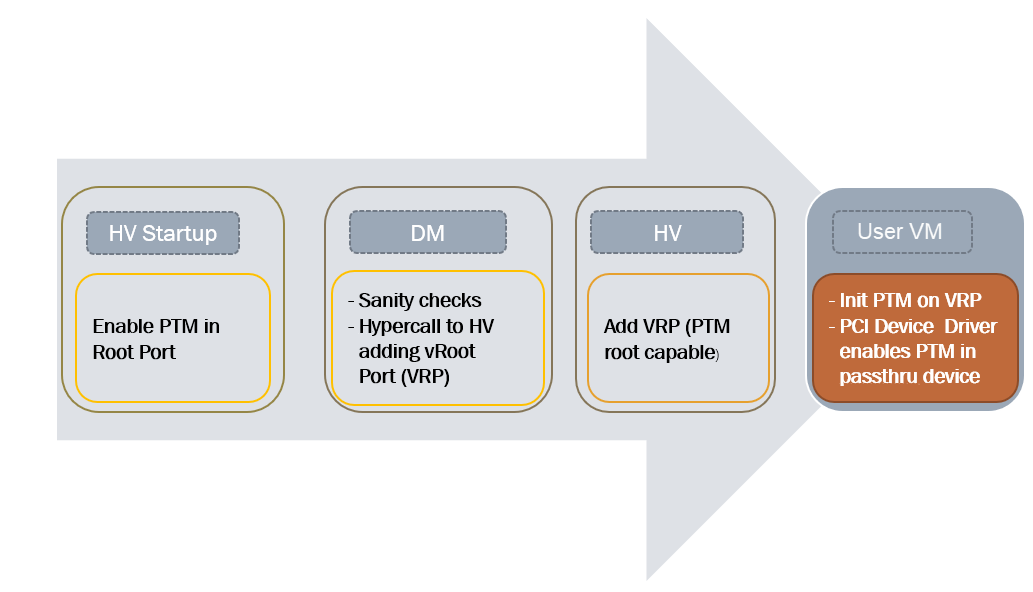
Figure 147 PTM-enabling Workflow in Post-launched VM
As shown in Figure 147, PTM is enabled in the root port during the
hypervisor startup. The Device Model (DM) then checks whether the passthrough
device supports PTM requestor capabilities and whether the corresponding root
port supports PTM root capabilities, as well as some other sanity checks. If an
error is detected during these checks, the error will be reported and ACRN will
not enable PTM in the post-launched VM. This doesn’t prevent the user from
launching the post-launched VM and passing through the device to the VM. If no
error is detected, the Device Model uses the add_vdev hypercall to add a
virtual root port (VRP), acting as the PTM root, to the post-launched VM before
passing through the device to the post-launched VM.
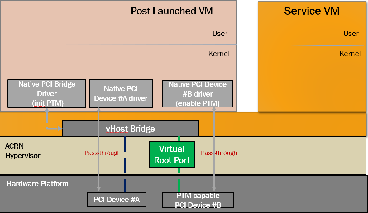
Figure 148 PTM-enabled PCI Device Passthrough to Post-launched VM
Figure 148 shows that, after enabling PTM, the passthrough device connects to the virtual root port instead of the virtual host bridge.
To use PTM in a virtualized environment, you may want to first verify that PTM is supported by the device and is enabled on the bare metal machine. If supported, follow these steps to enable PTM in the post-launched VM:
Make sure that PTM is enabled in the guest kernel. In the Linux kernel, for example, set
CONFIG_PCIE_PTM=y.Not every PCI device supports PTM. One example that does is the Intel I225-V Ethernet controller. If you passthrough this card to the post-launched VM, make sure the post-launched VM uses a version of the IGC driver that supports PTM.
In the Device Model launch script, add the
enable_ptmoption to the passthrough device. For example:$ acrn-dm -m $mem_size -s 0:0,hostbridge \ -s 3,virtio-blk,user-vm-test.img \ -s 4,virtio-net,tap=tap0 \ -s 5,virtio-console,@stdio:stdio_port \ -s 6,passthru,a9/00/0,enable_ptm \ --ovmf /usr/share/acrn/bios/OVMF.fd \
You can check that PTM is correctly enabled on the post-launched VM by displaying the PCI bus hierarchy on the post-launched VM using the
lspcicommand:lspci -tv -[0000:00]-+-00.0 Network Appliance Corporation Device 1275 +-03.0 Red Hat, Inc. Virtio block device +-04.0 Red Hat, Inc. Virtio network device +-05.0 Red Hat, Inc. Virtio console \-06.0-[01]----00.0 Intel Corporation Device 15f2 sudo lspci -vv # (Only relevant output is shown) 00:00.0 Host bridge: Network Appliance Corporation Device 1275 00:06.0 PCI bridge: Intel Corporation Sunrise Point-LP PCI Express Root Port #5 (rev 02) (prog-if 00 [Normal decode]) . . . Capabilities: [100 v1] Precision Time Measurement PTMCap: Requester:- Responder:+ Root:+ PTMClockGranularity: 4ns PTMControl: Enabled:+ RootSelected:+ PTMEffectiveGranularity: 4ns Kernel driver in use: pcieport 01:00.0 Ethernet controller: Intel Corporation Device 15f2 (rev 01) . . . Capabilities: [1f0 v1] Precision Time Measurement PTMCap: Requester:+ Responder:- Root:- PTMClockGranularity: 4ns PTMControl: Enabled:+ RootSelected:- PTMEffectiveGranularity: 4ns Kernel driver in use: igc
API Data Structures and Interfaces
The following are common APIs provided to initialize interrupt remapping for VMs:
-
int32_t ptirq_intx_pin_remap(struct acrn_vm *vm, uint32_t virt_gsi, enum intx_ctlr vgsi_ctlr)
INTx remapping for passthrough device.
Set up the remapping of the given virtual pin for the given vm. This is the main entry for PCI/Legacy device assignment with INTx, calling from vIOAPIC or vPIC.
- Preconditions
vm != NULL
- Parameters
vm – [in] pointer to acrn_vm
virt_gsi – [in] virtual GSI number associated with the passthrough device
vgsi_ctlr – [in] INTX_CTLR_IOAPIC or INTX_CTLR_PIC
- Returns
0: on success
-ENODEV:for Service VM, the entry already be held by others
for User VM, no pre-hold mapping found.
-
int32_t ptirq_prepare_msix_remap(struct acrn_vm *vm, uint16_t virt_bdf, uint16_t phys_bdf, uint16_t entry_nr, struct msi_info *info, uint16_t irte_idx)
MSI/MSI-x remapping for passthrough device.
Main entry for PCI device assignment with MSI and MSI-X. MSI can up to 8 vectors and MSI-X can up to 1024 Vectors.
- Preconditions
vm != NULL
- Preconditions
info != NULL
- Parameters
vm – [in] pointer to acrn_vm
virt_bdf – [in] virtual bdf associated with the passthrough device
phys_bdf – [in] virtual bdf associated with the passthrough device
entry_nr – [in] indicate coming vectors, entry_nr = 0 means first vector
info – [in] structure used for MSI/MSI-x remapping
irte_idx – [in] caller can pass a valid IRTE index, otherwise, use INVALID_IRTE_ID
- Returns
0: on success
-ENODEV:for Service VM, the entry already be held by others
for User VM, no pre-hold mapping found.
Post-launched VMs need to pre-allocate interrupt entries during VM initialization. Post-launched VMs need to free interrupt entries during VM de-initialization. The following APIs are provided to pre-allocate/free interrupt entries for post-launched VMs:
-
int32_t ptirq_add_intx_remapping(struct acrn_vm *vm, uint32_t virt_gsi, uint32_t phys_gsi, bool pic_pin)
Add an interrupt remapping entry for INTx as pre-hold mapping.
Except Service VM, Device Model should call this function to pre-hold ptdev intx The entry is identified by phys_pin, one entry vs. one phys_pin. Currently, one phys_pin can only be held by one pin source (vPIC or vIOAPIC).
- Preconditions
vm != NULL
- Parameters
vm – [in] pointer to acrn_vm
virt_gsi – [in] virtual pin number associated with the passthrough device
phys_gsi – [in] physical pin number associated with the passthrough device
pic_pin – [in] true for pic, false for ioapic
- Returns
0: on success
-EINVAL:invalid virt_pin value-ENODEV:failed to add the remapping entry
-
void ptirq_remove_intx_remapping(const struct acrn_vm *vm, uint32_t gsi, bool pic_pin, bool is_phy_gsi)
Remove an interrupt remapping entry for INTx.
Deactivate & remove mapping entry of the given virt gsi for given vm or phys gsi assigned to this vm.
- Preconditions
vm != NULL
- Parameters
vm – [in] pointer to acrn_vm
gsi – [in] virtual gsi number or physical gsi number associated with the passthrough device
pic_pin – [in] true for pic, false for ioapic
is_phy_gsi – [in] true if gsi is physical, false if gsi is virtual
-
void ptirq_remove_msix_remapping(const struct acrn_vm *vm, uint16_t phys_bdf, uint32_t vector_count)
Remove interrupt remapping entry/entries for MSI/MSI-x.
Remove the mapping of given number of vectors of the given virtual BDF for the given vm.
- Preconditions
vm != NULL
- Parameters
vm – [in] pointer to acrn_vm
phys_bdf – [in] physical bdf associated with the passthrough device
vector_count – [in] number of vectors
The following APIs are provided to acknowledge a virtual interrupt:
-
void ptirq_intx_ack(struct acrn_vm *vm, uint32_t virt_gsi, enum intx_ctlr vgsi_ctlr)
Acknowledge a virtual interrupt for passthrough device.
Acknowledge a virtual legacy interrupt for a passthrough device.
- Preconditions
vm != NULL
- Parameters
vm – [in] pointer to acrn_vm
virt_gsi – [in] virtual GSI number associated with the passthrough device
vgsi_ctlr – [in] INTX_CTLR_IOAPIC or INTX_CTLR_PIC
The following APIs are provided to handle a ptdev interrupt:
-
void ptdev_init(void)
Passthrough device global data structure initialization.
During the hypervisor cpu initialization stage, this function:
init global spinlock for ptdev (on BSP)
register SOFTIRQ_PTDEV handler (on BSP)
init the softirq entry list for each CPU
-
void ptirq_softirq(uint16_t pcpu_id)
Handler of softirq for passthrough device.
When hypervisor receive a physical interrupt from passthrough device, it will enqueue a ptirq entry and raise softirq SOFTIRQ_PTDEV. This function is the handler of the softirq, it handles the interrupt and injects the virtual into VM. The handler is registered by calling ptdev_init during hypervisor initialization.
- Parameters
pcpu_id – [in] physical cpu id of the soft irq
-
struct ptirq_remapping_info *ptirq_alloc_entry(struct acrn_vm *vm, uint32_t intr_type)
Allocate a ptirq_remapping_info entry.
Allocate a ptirq_remapping_info entry for hypervisor to store the remapping information. The total number of the entries is statically defined as CONFIG_MAX_PT_IRQ_ENTRIES. Appropriate number should be configured on different platforms.
- Parameters
vm – [in] acrn_vm that the entry allocated for.
intr_type – [in] interrupt type: PTDEV_INTR_MSI or PTDEV_INTR_INTX
- Return values
NULL – when the number of entries allocated is CONFIG_MAX_PT_IRQ_ENTRIES
!NULL – when the number of entries allocated is less than CONFIG_MAX_PT_IRQ_ENTRIES
-
void ptirq_release_entry(struct ptirq_remapping_info *entry)
Release a ptirq_remapping_info entry.
- Parameters
entry – [in] the ptirq_remapping_info entry to release.
-
void ptdev_release_all_entries(const struct acrn_vm *vm)
Deactivate and release all ptirq entries for a VM.
This function deactivates and releases all ptirq entries for a VM. The function should only be called after the VM is already down.
- Preconditions
VM is already down
- Parameters
vm – [in] acrn_vm on which the ptirq entries will be released
-
int32_t ptirq_activate_entry(struct ptirq_remapping_info *entry, uint32_t phys_irq)
Activate a irq for the associated passthrough device.
After activating the ptirq entry, the physical interrupt irq of passthrough device will be handled by the handler ptirq_interrupt_handler.
- Parameters
entry – [in] the ptirq_remapping_info entry that will be associated with the physical irq.
phys_irq – [in] physical interrupt irq for the entry
- Return values
success – when return value >=0
failure – when return value < 0
-
void ptirq_deactivate_entry(struct ptirq_remapping_info *entry)
De-activate a irq for the associated passthrough device.
- Parameters
entry – [in] the ptirq_remapping_info entry that will be de-activated.
-
struct ptirq_remapping_info *ptirq_dequeue_softirq(uint16_t pcpu_id)
Dequeue an entry from per cpu ptdev softirq queue.
Dequeue an entry from the ptdev softirq queue on the specific physical cpu.
- Parameters
pcpu_id – [in] physical cpu id
- Return values
NULL – when the queue is empty
!NULL – when there is available ptirq_remapping_info entry in the queue
-
uint32_t ptirq_get_intr_data(const struct acrn_vm *target_vm, uint64_t *buffer, uint32_t buffer_cnt)
Get the interrupt information and store to the buffer provided.
- Parameters
target_vm – [in] the VM to get the interrupt information.
buffer – [out] where interrupt information is stored.
buffer_cnt – [in] the size of the buffer.
- Return values
the – actual size the buffer filled with the interrupt information