UART Virtualization
In ACRN, UART virtualization is implemented as a fully-emulated device. In the Service OS (SOS), UART virtualization is implemented in the hypervisor itself. In the User OS (UOS), UART virtualization is implemented in the Device Model (DM), and is the primary topic of this document. We’ll summarize differences between the hypervisor and DM implementations at the end of this document.
UART emulation is a typical full-emulation implementation and is a good example to learn about I/O emulation in a virtualized environment. There is a detailed explanation about the I/O emulation flow in ACRN in ACRN I/O mediator.
Architecture
The ACRN DM architecture for UART virtualization is shown here:
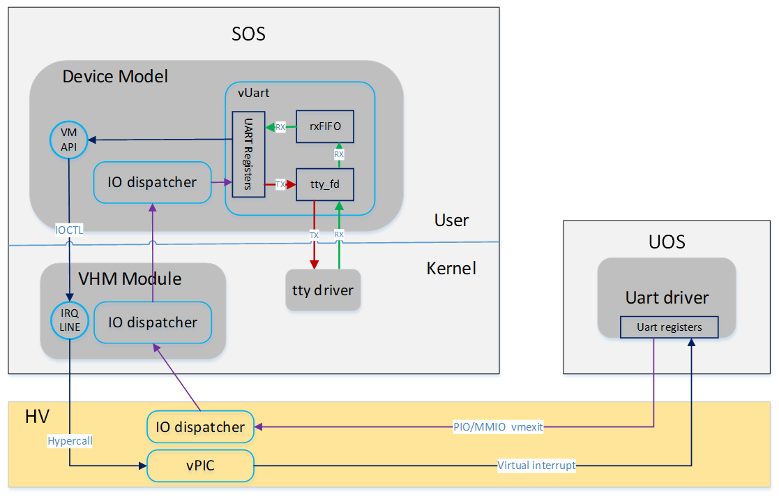
Figure 88 Device Model’s UART virtualization architecture
There are three objects used to emulate one UART device in DM: UART registers, rxFIFO, and backend tty devices.
UART registers are emulated by member variables in struct
uart_vdev, one variable for each register. These variables are used
to track the register status programed by the frontend driver. The
handler of each register depends on the register’s functionality.
A FIFO is implemented to emulate RX. Normally characters are read
from the backend tty device when available, then put into the rxFIFO.
When the Guest application tries to read from the UART, the access to
register com_data causes a vmexit. Device model catches the
vmexit and emulates the UART by returning one character from rxFIFO.
Note
When com_fcr is available, the Guest application can write
0 to this register to disable rxFIFO. In this case the rxFIFO in
device model degenerates to a buffer containing only one character.
When the Guest application tries to send a character to the UART, it
writes to the com_data register, which will cause a vmexit as
well. Device model catches the vmexit and emulates the UART by
redirecting the character to the backend tty device.
The UART device emulated by the ACRN device model is connected to the system by
the LPC bus. In the current implementation, two channel LPC UARTs are I/O mapped to
the traditional COM port addresses of 0x3F8 and 0x2F8. These are defined in
global variable uart_lres.
There are two options needed for configuring the UART in the arcn-dm
command line. First, the LPC is defined as a PCI device:
-s 1:0,lpc
The other option defines a UART port:
-l com1,stdio
The first parameter here is the name of the UART (must be “com1” or
“com2”). The second parameter is species the backend
tty device: stdio or a path to the dedicated tty device
node, for example /dev/pts/0.
If you are using a specified tty device, find the name of the terminal
connected to standard input using the tty command (e.g.,
/dev/pts/1). Use this name to define the UART port on the acrn-dm
command line, for example:
-l com1,/dev/pts/1
When arcn-dm starts, pci_lpc_init is called as the callback of the
vdev_init of the PCI device given on the acrn-dm command line.
Later, lpc_init is called in pci_lpc_init. lpc_init iterates
on the available UART instances defined on the command line and
initializes them one by one. register_inout is called on the port
region of each UART instance, enabling access to the UART ports to be
routed to the registered handler.
In the case of UART emulation, the registered handlers are uart_read
and uart_write.
A similar virtual UART device is implemented in the hypervisor. Currently UART16550 is owned by the hypervisor itself and is used for debugging purposes. (The UART properties are configured by parameters to the hypervisor command line.) The hypervisor emulates a UART device with 0x3F8 address to the SOS and acts as the SOS console. The general emulation is the same as used in the device model, with the following differences:
- PIO region is directly registered to the vmexit handler dispatcher via
vuart_register_io_handler - Two FIFOs are implemented, one for RX, the other of TX
- RX flow:
- Characters are read from the UART HW into a 2048-byte sbuf,
triggered by
console_read - Characters are read from the sbuf and put to rxFIFO,
triggered by
vuart_console_rx_chars - A virtual interrupt is sent to the SOS that triggered the read,
and characters from rxFIFO are sent to the SOS by emulating a read
of register
UART16550_RBR
- Characters are read from the UART HW into a 2048-byte sbuf,
triggered by
- TX flow:
- Characters are put into txFIFO by emulating a write of register
UART16550_THR - Characters in txFIFO are read out one by one, and sent to the console
by printf, triggered by
vuart_console_tx_chars - Implementation of printf is based on the console, which finally sends
characters to the UART HW by writing to register
UART16550_RBR
- Characters are put into txFIFO by emulating a write of register